00197042-04_SM_X-Serie-S_Customer_EN.pdf - 第322页
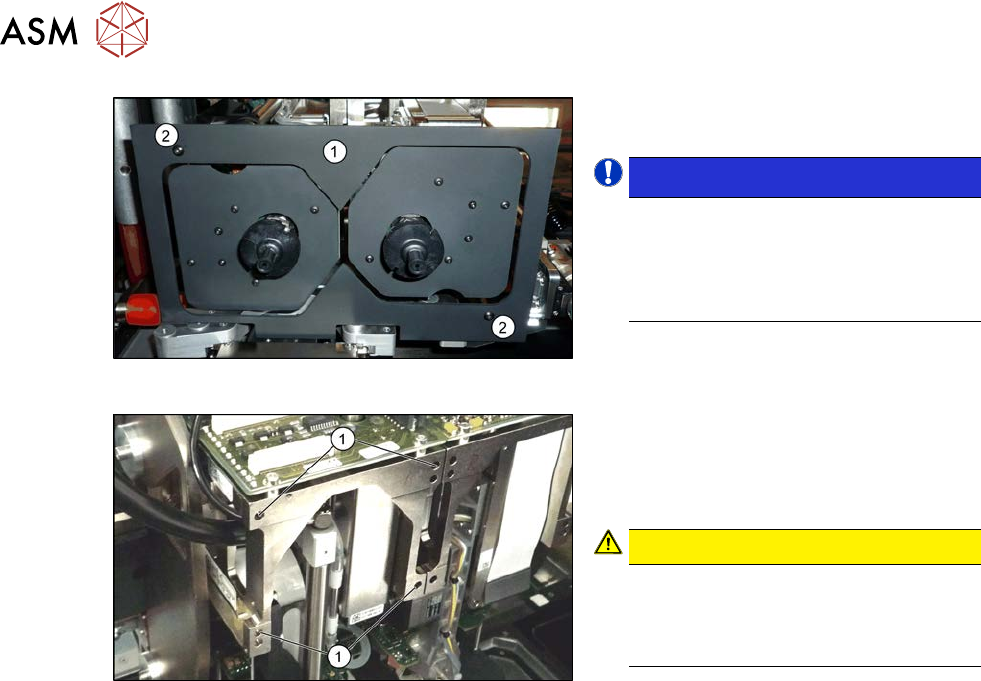
8 Head exchange 8.7 Replacing the SIPLACE Twin 322 Service Manual SIPLACE X-Serie S 06/2019 Fig.414: Camera lens hood ► Remove the camera screen (1) . This is fastened with two black screws (2) . NOTICE! Only use …
8 Head exchange
8.7 Replacing the SIPLACE Twin
Service Manual SIPLACE X-Serie S 06/2019 321
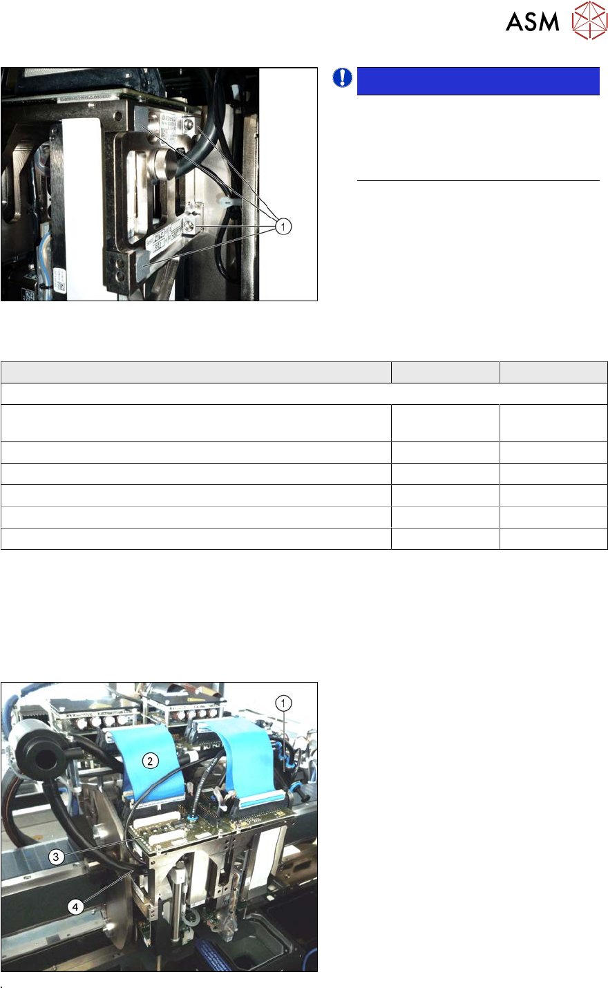
Fig.412: Undetachable screws
NOTICE!
When using modules with Undetach-
able screws(1) you may need to fit
these screws on the other side de-
pending on the installation position.
.
Observe the various different hose lengths:
Designation Item no. Length
Other hoses on the machine:
Hose supplied "Silicon hose Di8 Da12 electrically conductive
1m“
03006727Sxx
●
Cooling air hose X motor
03006777-xx 180 mm
●
Cooling air hose P+P module right
03006779-xx 395 mm
●
Cooling air hose P+P module left
03006780-xx 230 mm
●
Cooling air hose X motor TX
03126503-xx 210 mm
●
Cooling air hose X motor rotated gantry
03059420-xx 440 mm
Removal
► Switch off the machine, disconnect it from the power supply and secure it to prevent
unauthorized reactivation.
1.2 "Preparatory work..." [}16]
► Switch off the compressed air supply
5.2 "Disabling the compressed air supply" [}134]
Fig.413: Connectors
► Move the gantry into a position which
allows you best access.
► Unplug the pneumatic connection from
the Twin vacuum generator to the
pneumatic distributor(1) and from the
silencer.
► Disconnect the exhaust air silicone
hose from the Twin vacuum generator
(4).
► Unplug the pneumatic connection from
the pneumatic distributor(1) to the
Twin return cylinder.
► Unplug the flat ribbon cable(2) from
the head main board(3) on the Twin.
8 Head exchange
8.7 Replacing the SIPLACE Twin
322 Service Manual SIPLACE X-Serie S 06/2019
Fig.414: Camera lens hood
► Remove the camera screen(1). This is
fastened with two black screws(2).
NOTICE!
Only use these black screws to fix the
camera lens hood. This prevents re-
flection when measuring components
with the stationary camera.
.
Fig.415: Fastening screws
Each module is fixed with four screws to the
head plate and is positioned with two pins.
► Remove the four M4x14 fastening
screws (1) with a long Allen key.
CAUTION!
Hold tight!
Hold the module tight before removing
the last of the four screws. The module
could otherwise fall down.
.
► Pull the module out of the locating pins.
► Placing the head into the head transport box
Installation
► Follow the removal instructions in reverse order for installation. Also observe the following
instructions:
– Fit the fastening screws on the other side of the module, if needed (see above).
– Make a note of the force values for the new module. These force values can be found on a
label at the side of the module.
– Make sure that the assembly position is correct.
– Perform a head calibration.
1.2 "Preparatory work..." [}16]
5.2 "Disabling the compressed air supply" [}134]
See also
2 8.8 "Installation Positions on the Head Plate" [}323]
2 8.9 "Calibration" [}324]
2 8.9.2 "Calibrating the heads and cameras (SW70x)" [}325]
8 Head exchange
8.8 Installation Positions on the Head Plate
Service Manual SIPLACE X-Serie S 06/2019 323
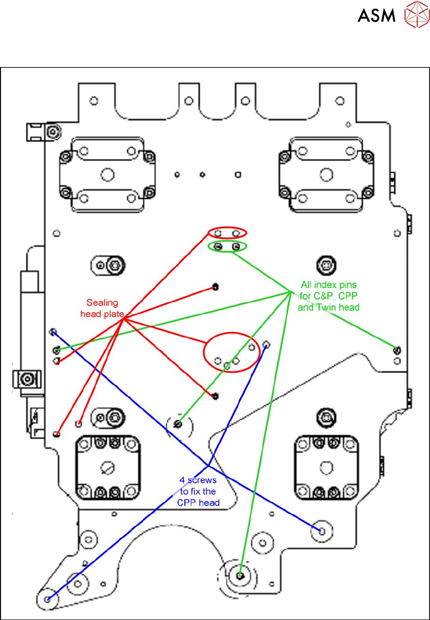
8.8 Installation Positions on the Head Plate
Fig.416: Installation positions on the head plate