00197042-04_SM_X-Serie-S_Customer_EN.pdf - 第324页
8 Head exchange 8.9 Calibration 324 Service Manual SIPLACE X-Serie S 06/2019 8.9 Calibration Overview With the calibration of the component camera the following values are determined: the relationship of "camera pix…
8 Head exchange
8.8 Installation Positions on the Head Plate
Service Manual SIPLACE X-Serie S 06/2019 323
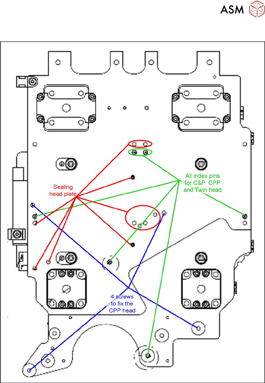
8.8 Installation Positions on the Head Plate
Fig.416: Installation positions on the head plate

8 Head exchange
8.9 Calibration
324 Service Manual SIPLACE X-Serie S 06/2019
8.9 Calibration
Overview
With the calibration of the component camera the following values are determined:
the relationship of "camera pixel size to resolution of machine measuring system (X,Y)", the "cam-
era center point in X and Y direction" and the "torsion angle of the CCD sensor in the camera". This
is following by determining the head offset and the segment offsets for the top and bottom.
●
Head offset: the head offset is the distance between the PCB camera and the nozzle (seg-
ment1). The target is a fixed value (X=0 and Y=‑105mm) to which an offset value (from the
head calibration) is added.
●
Segment offset top: the top segment offset involves turning the calibration tool in the compo-
nent camera in 0°, 90°, 180° and 270°. The value determined is that of the rotating center of
the nozzle tip in relation to the component camera center in the X and Y direction.
●
Segment offset bottom: the bottom segment offset involves recording and measuring the
calibration tool in the 0°, 90°, 180° and 270° positions. The value determined is that of the ro-
tating center point of the nozzle tip when the Z axis is extended in relation to the PCB camera.
Segment 1 is the reference (X=0, °Y=0) for the other segments.
8.9.1 Calibration procedure
► Machine zero point
► PCB camera
– Camera coefficient (illustration scale in nm/pixel)
– Calibration of PCB camera center point
– Calibration of PCB camera rotation to machine coordinate system
► Calibration tool position (optional)
► Travel distance X/Y axis (optional)
– Calibration of min/max gantry travel distances
► Placement head
– Pressure control valve (SIPLACE C&P20P)
– Camera coefficient (unit nm/pixel), angle
– Head offset (offset PCB camera to component camera)
– Segment offset II (bottom)
– Segment offset I (top)
► Nozzle changers
– Calibration of pickup position for all magazines
– Calibration of pickup height
– Calibration of reject position
8 Head exchange
8.9 Calibration
Service Manual SIPLACE X-Serie S 06/2019 325
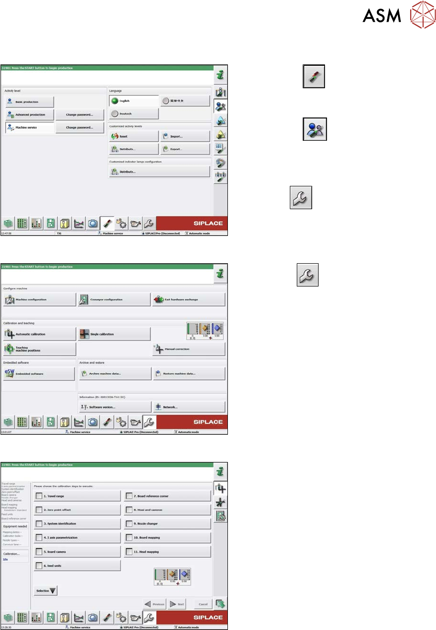
8.9.2 Calibrating the heads and cameras (SW70x)
Fig.417: Select operator level
► Select the
button, to open the
Configure, update and calibrate the
machine menu.
► Select the
button to open the
Check and set user settings menu.
► Switch over to the operator level Ma-
chine service.
ð The
button will be shown.
Fig.418: Service Menu
► Click the
button to enter the Ser-
vice menu.
► Click the Automatic calibration but-
ton.
Fig.419: Automatic Calibration
► Select Heads and cameras.
► Click on the Continue button.
Follow the instructions on the next pages:
► On the next page, select the gantries
on which the heads to be calibrated are
located and then click on the Next but-
ton.
► The next step is to check the calibration
conditions (nozzle, calibration tool etc.).
Follow the instructions provided.
After this step, calibration will begin. All re-
quired intermediate steps (head height etc.)
will be performed automatically.