00197042-04_SM_X-Serie-S_Customer_EN.pdf - 第337页
9 Component feeding 9.1 Cutter Service Manual SIPLACE X-Serie S 06/2019 337 Removing the articulated joint ► Switch off the machine, disconnect it from the power supply and secure it to prevent unauthorized reactivation.…
9 Component feeding
9.1 Cutter
336 Service Manual SIPLACE X-Serie S 06/2019
Installation
► Follow the removal instructions in reverse order for installation. Also observe the following
instructions:
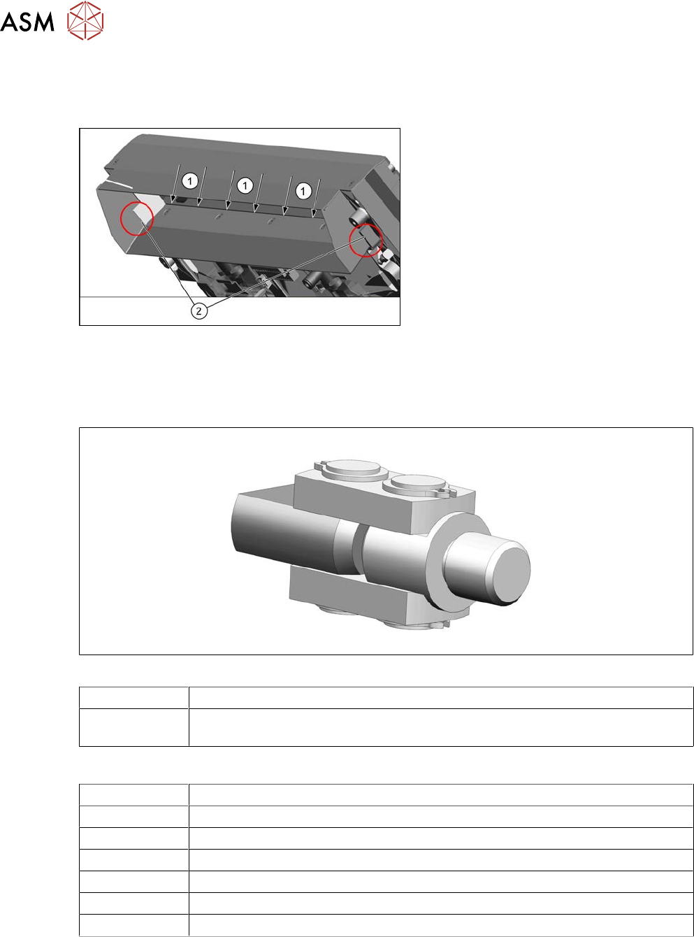
Fig.434: Fitting the protective plate
► Make sure that the five fastening
screws are completely countersunk.
The screws must be flush with the pro-
tective plate.
► Ensure that there is a gap between the
cutter blade and the edge of the baffle
plate inside(1).
► If everything is correct, there should be
a contact at position(2).
9.1.7 Replacing the articulated joint on the short-stroke cylinder
Parts
Fig.435: Joint
03000518-xx Articulated joint on the short-stroke cylinder
03057290-xx 2x hexagon socket fillister head screws ISO4762-M5x35-12.9, geomet. 321+VL
(screws for movable blade)
Equipment and tools
00376625‑xx Torque wrench 2.5‑25Nm
03121952-xx Lubrication grease BEM 34-132, 400 g cartridge
03123777-xx One-hand grease gun for 400 ml cartridge
00334892‑xx Loctite 243
00353832-xx Allen key set
Wire cutters
Cable ties
9 Component feeding
9.1 Cutter
Service Manual SIPLACE X-Serie S 06/2019 337
Removing the articulated joint
► Switch off the machine, disconnect it from the power supply and secure it to prevent
unauthorized reactivation.
1.2 "Preparatory work..." [}16]
► Remove the cutter from the machine.
9.1.3 "Replacing the Cutter on the COT Insert [03066690-xx]" [}329]
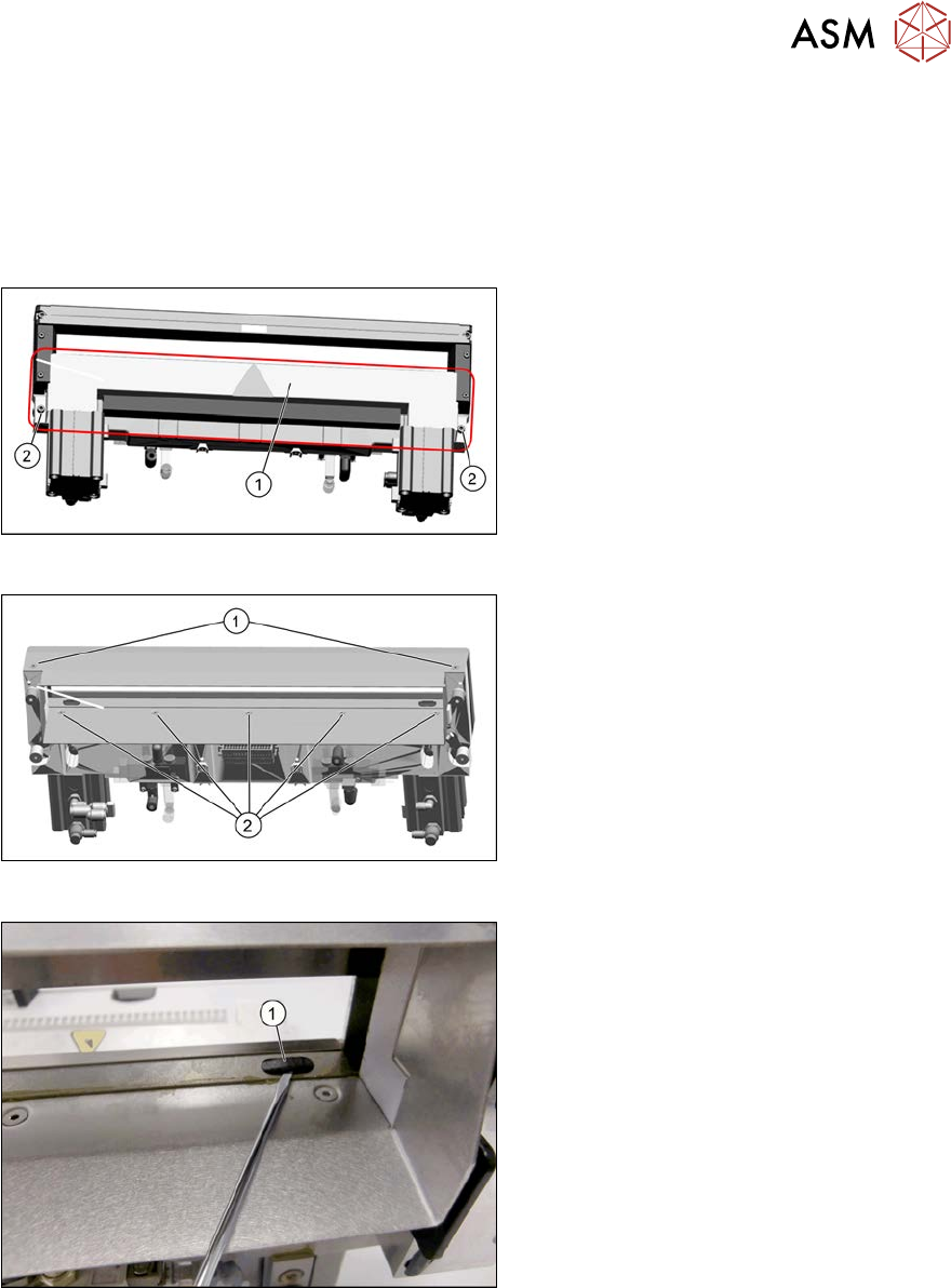
Fig.436: Cover plate
► Remove the screws(2) fastening the
top cover plate(1) and then remove the
top cover plate.
Fig.437: Baffle plate
► Remove the two screws(1) at the front
side and five screws(2) at the inner
side fastening the baffle plate.
► Remove the baffle plate unit from the
cutter.
Fig.438: Plastic caps
From the bottom side of the cutter you have
easy access to the plastic cap.
► Remove the plastic caps(1) over the
fastening screws on both sides of the
movable blade.
► Remove the two screws.
9 Component feeding
9.1 Cutter
338 Service Manual SIPLACE X-Serie S 06/2019
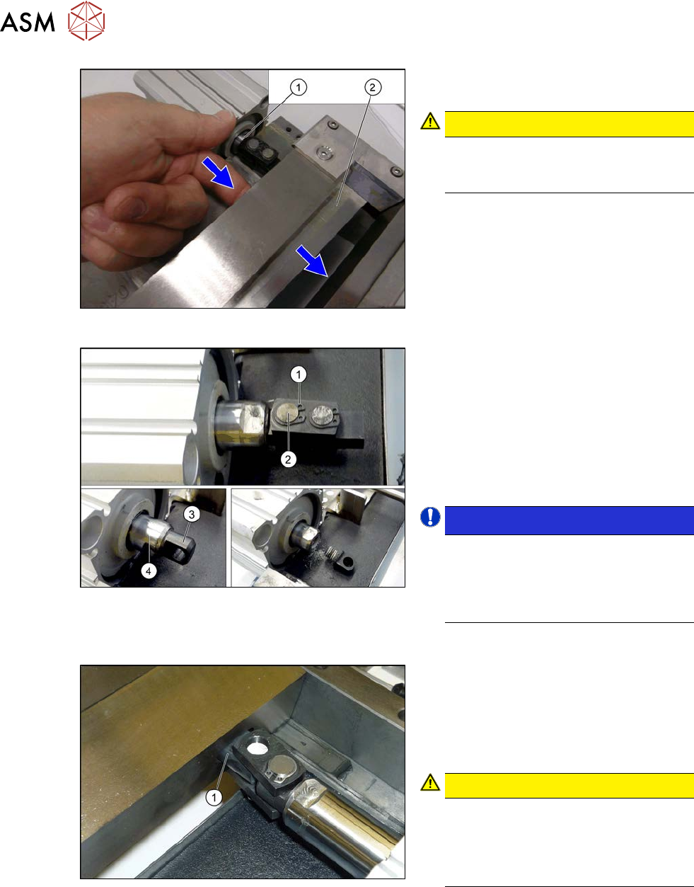
Fig.439: Movable blade
► Loosen the movable blade(2) from the
piston(1) of the short-stroke cylinder.
CAUTION!
Risk of injury!
There is a risk of injuring yourself on
the cutting edge of the blades.
.
Fig.440: Removing the articulated joint
► Remove the circlip (1).
► Push the piston rod a little into the
short-stroke cylinder and rotate the ar-
ticulated joint by 90degrees.
► Push the bolt(2) out of the articulated
joint.
► Unscrew the remaining articulated joint
adapter(3) from the piston(4).
NOTICE!
The adapter is secured with locking
varnish (Loctite no. 243). You will need
somewhat more strength than usual to
loosen it.
Hold against it with a spanner wrench.
.
Installation
Fig.441: Installing the articulated joint
► Screw the articulated joint into the
short-stroke cylinder with a torque of
22Nm. Make sure that the joint (1) is
horizontal so that it fits into the recess
in the moveable blade. Secure the
screw with Loctite243.
CAUTION!
Installation position
The articulated joint must be hori-
zontal. If not, the blades could be dis-
torted, which will then cause the joint
to break.
.
► Screw the articulated joint to the moveable blades. Tighten the screws to a torque of 6 Ncm.