00197042-04_SM_X-Serie-S_Customer_EN.pdf - 第340页
9 Component feeding 9.1 Cutter 340 Service Manual SIPLACE X-Serie S 06/2019 1 6 5 4 3 2 Fig.443: Removing the short-stroke cylinder ► Use a permanent marker to mark the exact installation position of the proxim- ity swi…
9 Component feeding
9.1 Cutter
Service Manual SIPLACE X-Serie S 06/2019 339
► Follow the removal instructions in reverse order for further installation. Also observe the fol-
lowing instructions:
– Grease the articulated joints with Klüber BEM 34-132.
– Secure the screws with Loctite 243.
– Insert the new screw caps. Remove the protruding plastic residues with a knife.
– Connect the compressed air hoses to the cylinder in the correct allocation.
– Check the gap between the leading edge of the wiper and the "empty-tape baffle, inside".
NOTICE
If the tapes are not cut correctly.
If the tapes are not cut correctly, even though the switching points have been set properly
and the short-stroke cylinder has been exchanged - complete with the one-way restrictor -
the cause of the problem may be:
► Incorrect compressed air level
► Leaking compressed air connection or Y-socket union
9.1.8 Replacing the short-stroke cylinder
Parts
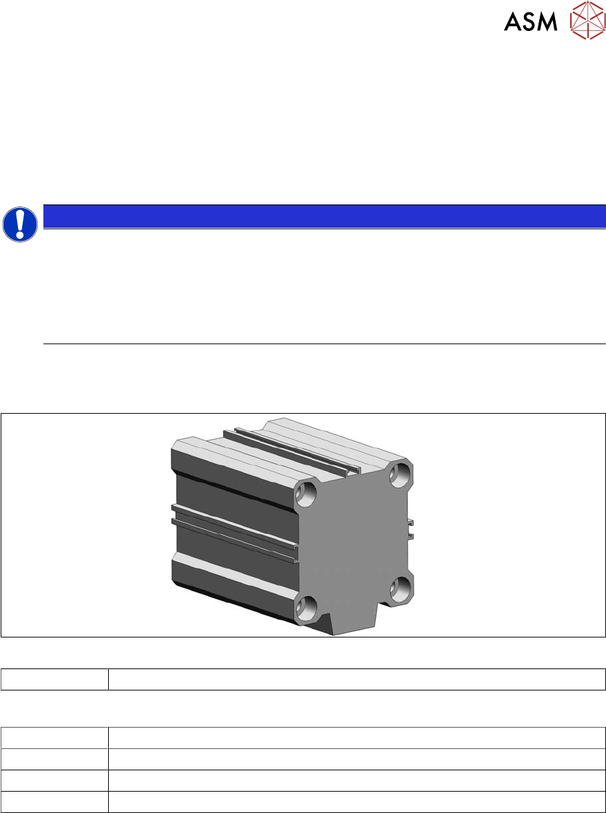
Fig.442: Short stroke cylinder
03038587-xx Short-stroke cylinder 50x40 ECDQ2B50-0040-CEJ00119
Equipment and tools
00334892‑xx Loctite 243
00353832-xx Allen key set
Wire cutters
Cable ties
Removal
► Switch off the machine, disconnect it from the power supply and secure it to prevent
unauthorized reactivation.
1.2 "Preparatory work..." [}16]
► Remove the cutter from the machine.
9.1.3 "Replacing the Cutter on the COT Insert [03066690-xx]" [}329]
► Remove the articulated joint from the short-stroke cylinder (5).
9.1.7 "Replacing the articulated joint on the short-stroke cylinder" [}336]
9 Component feeding
9.1 Cutter
340 Service Manual SIPLACE X-Serie S 06/2019
1
6
5
4
3
2
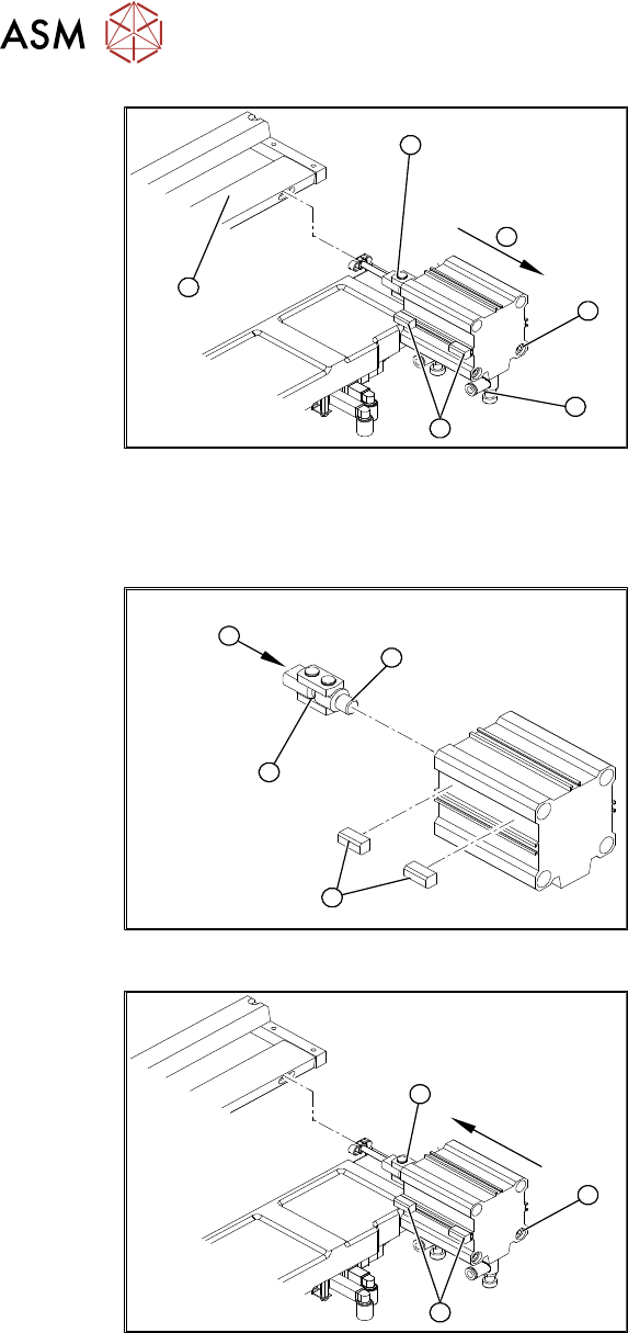
Fig.443: Removing the short-stroke cylinder
► Use a permanent marker to mark the
exact installation position of the proxim-
ity switch (1) on the short-stroke cylin-
der.
► Remove the screws fastening the two
inductive proximity switches (1) to the
short-stroke cylinder.
► Remove the compressed air connec-
tions (2) on the short-stroke cylinder.
You may want to mark their positions to
make clear assignment easier later on.
► Remove the two screws (3) fastening
the short-stroke cylinder.
► Remove the short-stroke cylinder (4)
from the cutter.
Installation
1
4
3
2
Fig.444: Fitting the articulated joint and proximity switches
► Apply a small amount of Loctite243 to
the thread (2) of the new articulated
joint.
► Screw the articulated joint (1) into the
short-stroke cylinder.
► Turn the articulated joint in its installa-
tion position(3).
Once the cylinder is installed, the slot in
the moveable blade prevents the articu-
lated joint from turning.
► Copy the exact installation position of
the proximity switch(4) onto the new
short-stroke cylinder (e.g. with a feeler
gauge, fine-tipped marker pen).
1
3
2
Fig.445: Fitting the short-stroke cylinder
► Fit the proximity switch (1) precisely in
the position you marked with the per-
manent marker.
► Place the prepared cylinder into the
cutter, in the correct rotary position of
the articulated joint (2).
► Fasten the cylinder in this position with
the two screws provided(3) (Loc-
tite243).
► Connect the compressed air hoses to the cylinder in the correct allocation.
► Further installation is performed by following the above instructions in the reverse order. Ob-
serve the following instructions:
– Also observe section 9.1.7 "Replacing the articulated joint on the short-stroke cylin-
der" [}336].
– From SW707.1: set the restrictors (see 9.1.13.1 "Times for Setting the Throttle on the Cut-
ter (From SW707.1)" [}352]).
9 Component feeding
9.1 Cutter
Service Manual SIPLACE X-Serie S 06/2019 341
9.1.9 Replacing the Cutter Blades
CAUTION
Risk of injury!
There is a high risk of injury from the blades and the wiper.
► Wear appropriately thick protective gloves!
► Never reach into the cutter from below or into the empty-tape duct from above.
► Make sure that no-one can injure themselves on the cutter after it has been dis-
mantled and placed next to the machine!
Parts
NOTICE
Turn the blade
The fixed and movable blades have been sharpened on both sides. If one side becomes
blunt, you can rotate the blade by 180 degrees to use the other side.
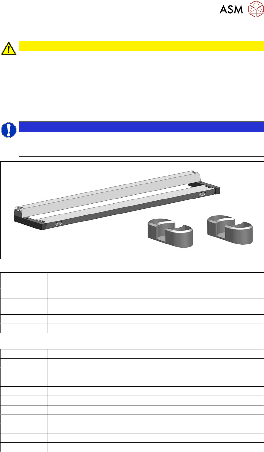
Fig.446: Set of blades and two blade covers
03009259-xx Set of blades aligned (tape cutter HF) (fits TX tape cutter, pneumatic
[03066690‑xx])
03000553-xx 2x blade cover (tape cutter HF) (cover for screws of movable blades)
03057290‑xx 2x hexagon socket fillister head screws ISO4762-M5x35-12.9, geomet 321+VL
(screws for movable blade)
03000518-xx 2x articulated joint (cutter HF)
03036943-xx 2x DIN71412-BM6 (lubrication nipple)
Equipment and tools
03121952-xx Lubrication grease BEM 34-132, 400 g cartridge
03123777-xx One-hand grease gun for 400 ml cartridge
03020782-xx Interflon Fin Grease
00334892‑xx Loctite 243
00091001-xx Extra protection gloves, leather
03078400‑xx Torque screwdriver ESD 1.0-5.0 Nm
00376625‑xx Torque wrench 2.5‑25Nm
03078706‑xx Bitholder f. Screwdriver TorqueVario
Allen key bit size 3-6
00096290-xx Fork wrench set
00094020-xx Feeler gauge size 20 - 0.05 - 1.0 mm