00197042-04_SM_X-Serie-S_Customer_EN.pdf - 第343页
9 Component feeding 9.1 Cutter Service Manual SIPLACE X-Serie S 06/2019 343 Fig.450: Movable blade ► Loosen the movable blade (2) from the piston (1) of the short-stroke cylinder. CAUTION! Risk of injury! There is a…
9 Component feeding
9.1 Cutter
342 Service Manual SIPLACE X-Serie S 06/2019
Brush
Cloth
Two large parallel clamps and a sturdy table with even surface, to clamp down
the dismantled cutter
00353832-xx Allen key set
Wire cutters
Cable ties
Removal
► Switch off the machine, disconnect it from the power supply and secure it to prevent
unauthorized reactivation.
1.2 "Preparatory work..." [}16]
► Remove the cutter from the machine.
9.1.3 "Replacing the Cutter on the COT Insert [03066690-xx]" [}329]
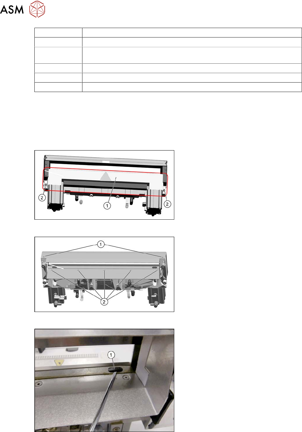
Fig.447: Cover plate
► Remove the screws(2) fastening the
top cover plate(1) and then remove the
top cover plate.
Fig.448: Baffle plate
► Remove the two screws(1) at the front
side and five screws(2) at the inner
side fastening the baffle plate.
► Remove the baffle plate unit from the
cutter.
Fig.449: Plastic caps
From the bottom side of the cutter you have
easy access to the plastic cap.
► Remove the plastic caps(1) over the
fastening screws on both sides of the
movable blade.
► Remove the two screws.
9 Component feeding
9.1 Cutter
Service Manual SIPLACE X-Serie S 06/2019 343
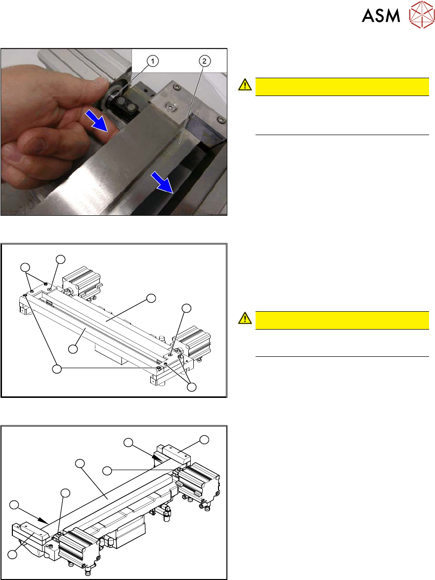
Fig.450: Movable blade
► Loosen the movable blade(2) from the
piston(1) of the short-stroke cylinder.
CAUTION!
Risk of injury!
There is a risk of injuring yourself on
the cutting edge of the blades.
.
4
3
5
1
4
3
2
Fig.451: Cutter
► Remove the two screws(1) fastening
the stationary blade(2).
► Remove the screws fastening the left
and right wipers (3) above the move-
able blade.
CAUTION!
Not all screws!
Do not loosen these two screws(4)
.
► Remove the wiper clip with the
wiper(5) and carefully place the whole
unit down (with the wiper facing
upwards).
3
4
1
5
4
3
2
Fig.452: Cutter
► Remove the right-hand downholder(1)
and the left downholder (2), plus the
spacers below.
► Use an SW10 open-ended wrench to
push against the joint (3), while loosen-
ing the hexagon socket-head screw of
the joint (4) in the moveable blade. This
may require more strength than usual
as the screws have been secured with
Loctite243.
► Grasp both ends of the moveable blade
(5) with the protective gloves and pull it
upwards and out.
9 Component feeding
9.1 Cutter
344 Service Manual SIPLACE X-Serie S 06/2019
Installation – requirements
CAUTION
Risk of injury!
There is a high risk of injury from the blades and the wiper.
●
Wear appropriately thick protective gloves!
●
Make sure all parts are clean before installing them.
●
Do not use fat dissolving agents on the blades (risk of rust film forming).
●
The new blades are covered with a fine lubrication film.
The blades may only be greased with the lubricants described in the maintenance manual.
Any other lubricant would impair the movement of the moveable blade.
●
If the new blades are not clean, carefully clean them (wear protective gloves) with a clean
brush or a well folded, clean and dry cloth.
Installation – preparations
1
6
5
4
3
2
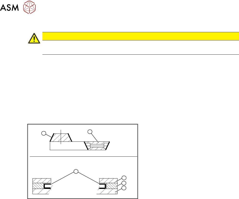
Fig.453: Blades
1. Stationary blade
2. Moveable blade
3. Sliding surfaces to be lubricated
4. Downholder
5. Spacer
6. Contact surface
► Make sure the cutter is in the correct rotary position (see the slant of the blade).
► Check the positioning of the individual blades to one another.
► Before installation, lubricate the sliding side surfaces of the moveable blade with Klüber BEM
34-132 and make sure that the recesses are filled. These will be refilled later on during main-
tenance with the lubrication nipples.