00197042-04_SM_X-Serie-S_Customer_EN.pdf - 第346页
9 Component feeding 9.1 Cutter 346 Service Manual SIPLACE X-Serie S 06/2019 Final work 1 2 Fig.456: Cutter (using example of X-Series) ► Use a feeler gauge to check the gap between the wiper (1) and the move- able blade…
9 Component feeding
9.1 Cutter
Service Manual SIPLACE X-Serie S 06/2019 345
Installation
2
3
4
1
4
3
2
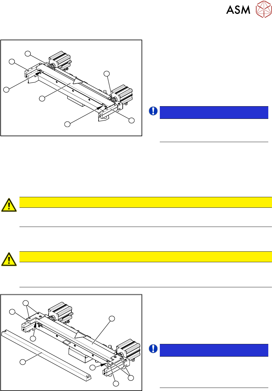
Fig.454: Cutter
► Correctly insert the moveable blade (1)
into the cutter and shift it along to its
original installation position.
► Apply Loctite243 to the two M4
screws to fasten the joint in the move-
able blade.
► Insert the screws (2) into the left and right
holes, provided in the moveable blade.
NOTICE!
Make sure that the joint (3) can slide into
the slot (=anti-twist function) in the
moveable blade without obstruction.
.
► Use an SW10 open-ended wrench to push against the relevant joint (3) and then tighten both
screws(2) to a torque of 6Nm.
► Fit the two caps over the fastening screws on the movable blade.
► Place the 2 new spacers (4) to the left and right of the moveable blade. The spacer side
marked with a number must face away from the blade.
CAUTION
The spacers and blades are matched!
► Do not use any spacers from other sets of blades.
► Lubricate the contact/slide surfaces for the moveable blade, as described in the section "Pre-
parations".
CAUTION
Only apply grease to the exact points required!
The overlapping cutting surfaces may only be greased with Interflon Fin grease [03020782-xx].
Also observe the preventive maintenance manual for your machine.
1
2
4
1
5
4
3
2
Fig.455: Cutter
► Place an adjusting plate (0.5 - 1.0 mm
thickness) on the left and right,
between the spacer and the front of the
movable blade (1).
► Place the previously removed down-
holder (2) onto the new spacers.
NOTICE!
Downholder
The downholders with version 03 are
those designed for cutters with version
04 (= with wiper).
.
► Insert the dismantled wiper unit (3) and the downholders and tighten loosely with the four
hexagon socket-head screws (4).
► Push the spacers (with inserted feeler gauges) as far as possible in the direction of the move-
able blade. The maximum permissible gap is 1.0 mm.
► Now tighten the four screws (4) crosswise at the downholder.
► Remove the two shim plates.
► Insert the new stationary blade (5) in the correct position and screw tight.
9 Component feeding
9.1 Cutter
346 Service Manual SIPLACE X-Serie S 06/2019
Final work
1
2
Fig.456: Cutter (using example of X-Series)
► Use a feeler gauge to check the gap
between the wiper (1) and the move-
able blade (2), along the entire length
and width of the blade.
ð The 0.05 mm feeler gauge should fit
through the gap.
ð The 0.25 mm feeler gauge should
not fit through the gap.
If the gap is not correct, check:
●
Whether the wrong downholder has
been installed (with function level < 03).
●
The downholders are those designed
for cutters with function status -04 (=
with wiper)!
●
Whether the blades, wiper etc. were
cleaned before installation.
If the gap is correct:
► Fit the baffle plate and cover plate. Make sure that the edges are parallel.
CAUTION
Check how the cables are run!
Make sure that the cables and hoses are not pinched or subjected to excess strain.
► Remove the clamps from the cutter/remove the cutter from the assembly plate.
► Further installation is performed by following the above instructions in the reverse order.
9.1.10 Replacing the wiper
Parts
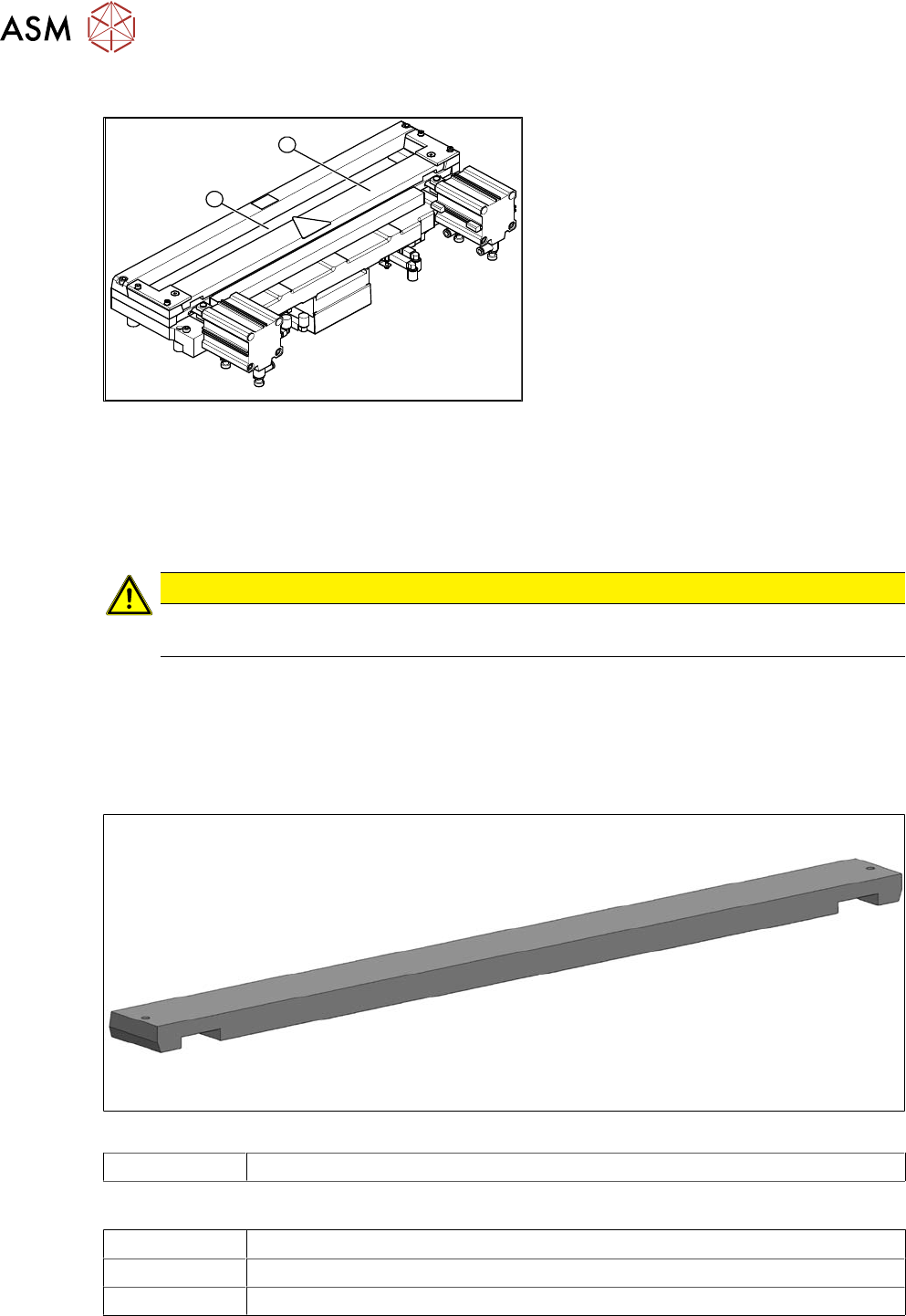
Fig.457: Wiper
03000491‑xx Wiper (cutter HF)
Equipment and tools
00353832-xx Allen key set
Wire cutters
Cable ties
9 Component feeding
9.1 Cutter
Service Manual SIPLACE X-Serie S 06/2019 347
Overview
Fig.458: Wiper on cutter
1. Wiper
Removal
► Switch off the machine, disconnect it from the power supply and secure it to prevent
unauthorized reactivation.
1.2 "Preparatory work..." [}16]
► Remove the cutter from the machine.
9.1.3 "Replacing the Cutter on the COT Insert [03066690-xx]" [}329]
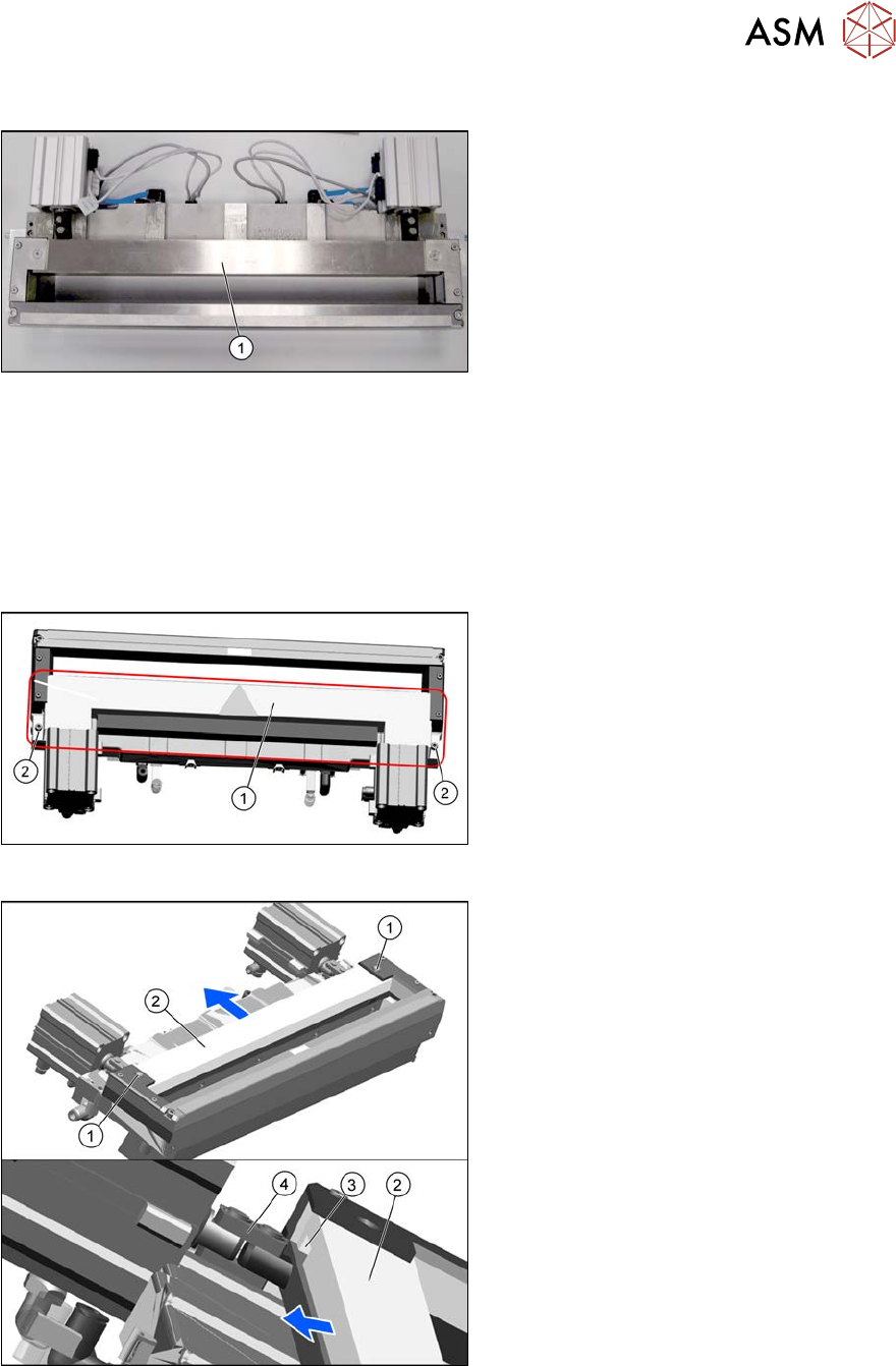
Fig.459: Cover plate
► Remove the screws(2) fastening the
top cover plate(1) and then remove the
top cover plate.
Fig.460: Removing the wiper
► Remove the two screws(1) fixing the
wiper(2).
► Remove the wiper(2).
The notch(3) in the wiper will move
over the articulated joint(4) on the
short-stroke cylinder.
Installation
► Follow the removal instructions in reverse order for installation.