00197042-04_SM_X-Serie-S_Customer_EN.pdf - 第372页
9 Component feeding 9.3 X-Series Component Trolley 372 Service Manual SIPLACE X-Serie S 06/2019 9.3 X-Series Component Trolley 9.3.1 SIPLACE X-series component trolley 1 4 3 2 Fig.497: SIPLACE X-series component trolley…
9 Component feeding
9.2 COT insert
Service Manual SIPLACE X-Serie S 06/2019 371
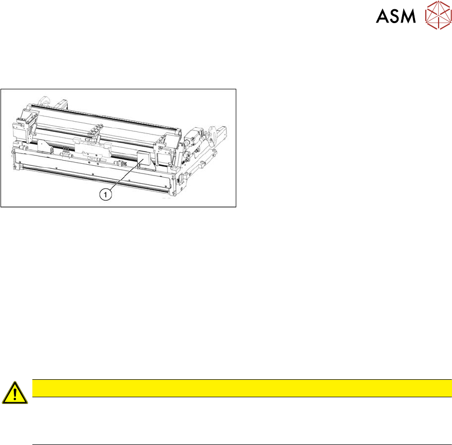
9.2.11 Replacing the infeed control
Parts, equipment and tools
Fig.496: Feed control
1. Infeed control assembly SX4
[03082077-xx]
Removal
► Switch off the machine and secure it to prevent unauthorized reactivation. Observe the
instructions in section 1.2 "Preparatory work..." [}16].
► Dismantle the nozzle changer over the infeed control (see 2.8.2 "Replacing the Nozzle
Changer" [}44]).
► To gain better access, you may need to disconnect the COT insert and pull it slightly out of
the machine. Observe the instructions in section 9.2.2 "Installation Positions of COT Insert and
Manual Table (Table Positions)" [}356].
Alternatively, you can improve access by removing the upper section of the component cam-
era.
CAUTION
Component camera
► The component camera mirror has sharp edges.
► Take care not to damage the component camera.
► Unplug all electrical connections to the insert control. You may want to mark their positions, to
make clear assignment easier later on.
► Remove the screws fastening the infeed control and remove the insert control from the
machine.
Installation
► Follow the removal instructions in reverse order for installation.
9 Component feeding
9.3 X-Series Component Trolley
372 Service Manual SIPLACE X-Serie S 06/2019
9.3 X-Series Component Trolley
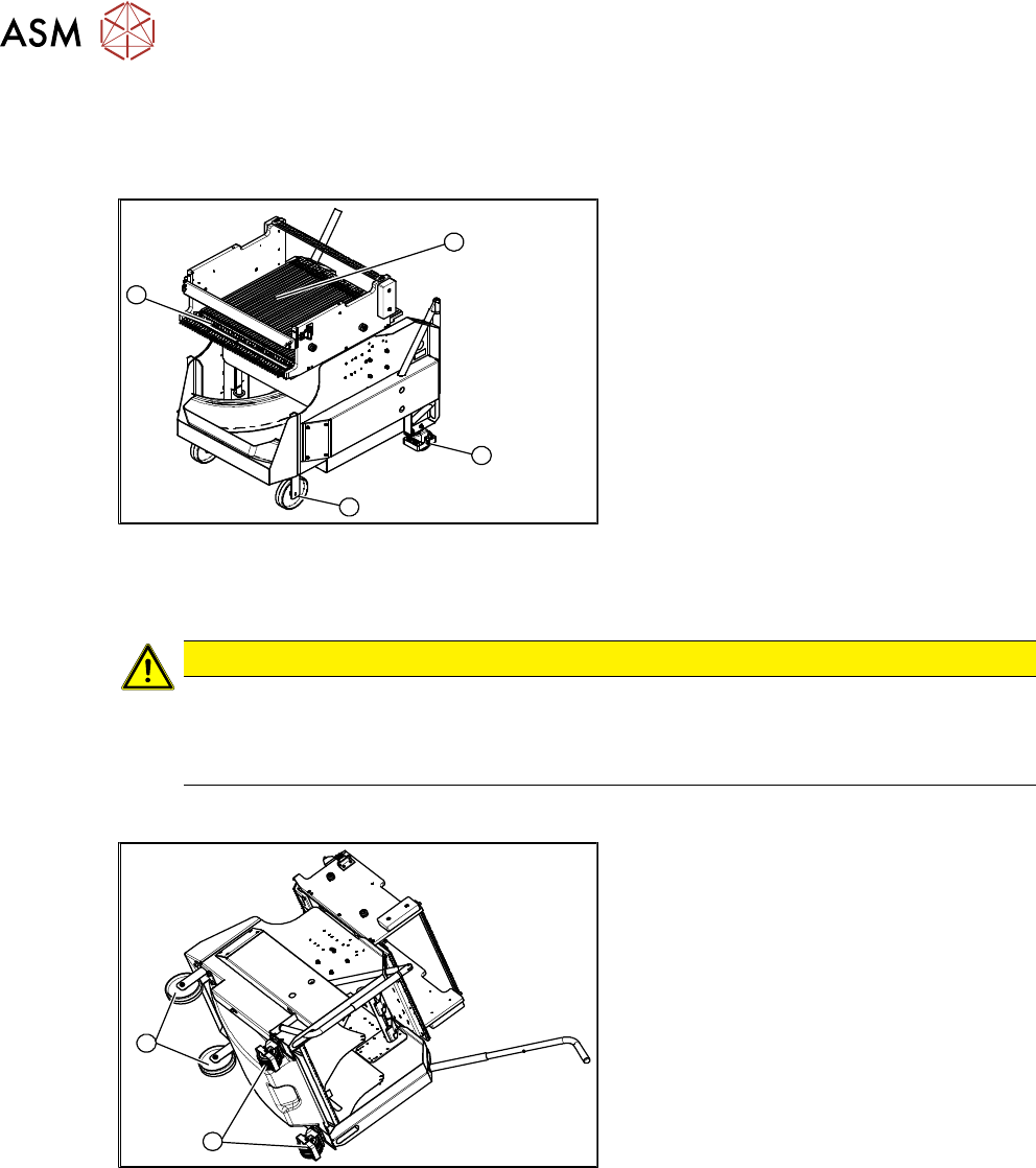
9.3.1 SIPLACE X-series component trolley
1
4
3
2
Fig.497: SIPLACE X-series component trolley
1. Guide castor
2. Fixed castor
3. Locking strip
4. Support block
9.3.2 Replacing the Fixed/Guide Castors [00341918-xx]
CAUTION
Heavy machine part!
The component trolley must be placed on one side in order to remove the fixed/guide
castors. The component changeover table is extremely heavy! You will need two people to
perform this task.
Parts, equipment and tools
1
2
Fig.498: Fixed and guide castors (example of SIPLACE
X‑Series shown)
1. Fixed castor [00341918-xx]
2. Guide castor [03004958-xx]
●
Second person
Removal/Installation
► Remove all feeders from the component trolley.
► Move the component trolley out of the machine.
► Place the component trolley down on its side, on a suitable surface.
► Undo the screws fastening the fixed/guide castor to to replaced and then remove the castor.
► Insert the new fixed/guide castor.
► Stand the component trolley on its wheels again.
9 Component feeding
9.3 X-Series Component Trolley
Service Manual SIPLACE X-Serie S 06/2019 373
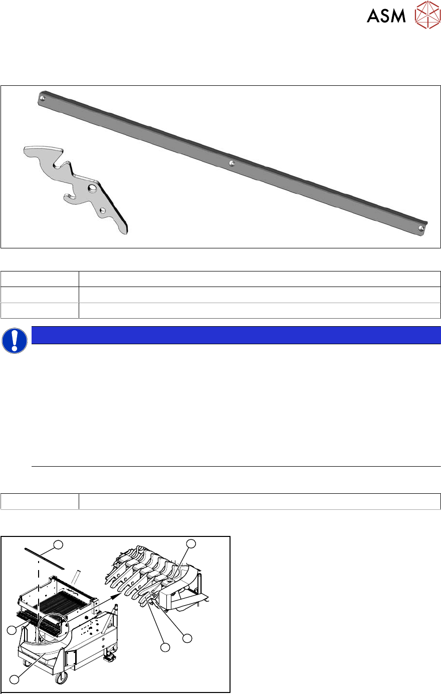
9.3.3 Replacing the locking latch
Parts
Fig.499: Locking latch and cover plate
03069205-xx Single locking latch
03077142-xx Cover plate for locking strip
03010352-xx Tension spring
NOTICE
SIPLACE TX/X/SX-Series component trolley
Component trolleys from the SIPLACE TX, SX and X-Series (S) require a locking latch for
each feeder track.
► Feeder lock [03023777-xx] with 40 locking latches
(1x per component trolley SIPLACE TX/X-Series (S)/SX4)
► Feeder lock [03057284-xx] with 30 locking latches
(1x per 30 track, 2x per 60 track component trolley SIPLACE SX1/SX2)
ð The feeder lock can also be completely dismantled from the component trolley and
replaced.
Equipment and tools
00353832-xx Allen key set
Overview
4
6
5
1
3
2
Fig.500: Locking latch on component trolley
1. Waste tape container
2. Cover
3. Position of complete feeder locking
mechanism
4. Locking latch
5. Tension spring
6. Pressure plate (under cover(2))