00197042-04_SM_X-Serie-S_Customer_EN.pdf - 第38页
2 Basic Machine 2.7 Replacing Stationary Component Camera Digital Type 25/33/36 38 Service Manual SIPLACE X-Serie S 06/2019 2.7.1 Installation Height of the Stationary Camera CAUTION Head crash danger An incorrect instal…
2 Basic Machine
2.7 Replacing Stationary Component Camera Digital Type 25/33/36
Service Manual SIPLACE X-Serie S 06/2019 37
2.7 Replacing Stationary Component Camera Digital Type
25/33/36
Refer to the appropriate assembly instructions:
●
Assembly instructions "SIPLACE X-Series S - Stationary Camera 25/33" [DE+EN: 00197397-xx]
●
Assembly instructions "SIPLACE X-Series S - Stationary Camera 25/33 GigE" [DE+EN:
00197710‑xx]
NOTICE
Subsequent installation or conversion of stationary cameras
Observe the following points, where necessary:
► "Incorrectly labeled spacers for stationary cameras" [DE: TI2014-02D04] [EN:
TI2014-02E04]
During retrofitting or conversion of stationary cameras or "Smart Pin Support Q10"
magazines, pay attention to correct fitting of the spacers.
► Assembly instructions "SIPLACE X-Series S - Smart Pin Support" [DE+EN:
00197394-xx]
NOTICE
Camera adaptor
You may need to fit an IC camera adaptor assembly (see assembly instructions).
► Location 1 to 3: IC camera adaptor assembly SX4a [03099054-xx]
► Location 4: IC camera adaptor assembly SP4 SX4a [03099004-xx]
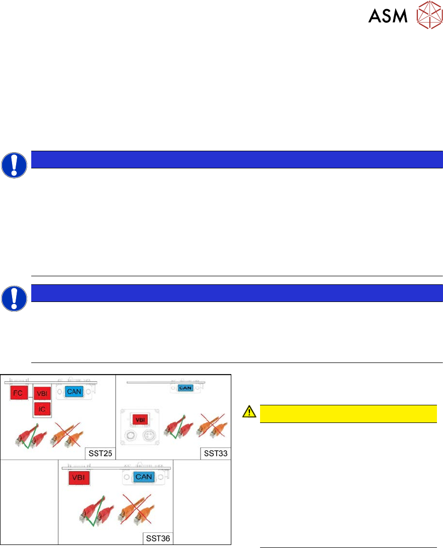
Fig.26: Cables
From machine number Hxxxx, the stationary
cameras fitted will have GigE.
CAUTION!
Pay attention to the correct cabling of
the stationary cameras.
Never install a GigE camera in an
older machine (up to machine number
Gxxxx) with Hotlink interface as this
will result in destruction of the camera!
The Hotlink interface can be identified
by the orange cables.
The GigE interface can be identified by
the red cables.
.
See also
2 2.7.4 "DIP Switch for Camera Types 25 and 33" [}42]
2 Basic Machine
2.7 Replacing Stationary Component Camera Digital Type 25/33/36
38 Service Manual SIPLACE X-Serie S 06/2019
2.7.1 Installation Height of the Stationary Camera
CAUTION
Head crash danger
An incorrect installation height can result in a head crash!
The installation height at which the camera can be installed depends on the camera version. You
will either only be able to use one specific height or will have the option of several installation
heights. The following description only applies for the following camera versions with three possible
installation heights:
●
Stationary component camera P&P (type 33) 55x45 digit. [03016339-xx] from version -06
●
Stationary component camera P&P (type 36) 32x32 digit. [03042491-xx] from version -04
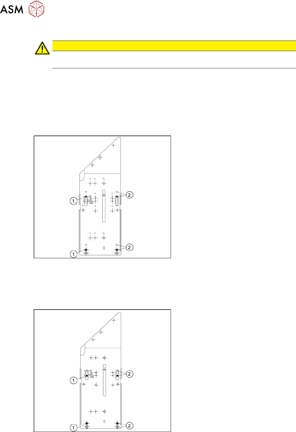
Stationary camera in position 1
Fig.27: Stationary camera in position 1
1. Screw
2. Thread in the machine frame
Position 1 has to be used in the following
cases:
●
SX1/SX2: always
●
SX4, X-Series: If at least one DLM or
CPP head is used in the corresponding
placement area.
Stationary camera in position 2
Position 2 is not relevant for the SX and the X-Series.
Stationary camera in position 3
Fig.28: Stationary camera in position 3
1. Screw
2. Thread in the machine frame
Position 3 has to be used in the following
cases:
●
SX1/SX2: never.
●
SX4, X-Series: If only TwinHeads are
used in the corresponding placement
area.

2 Basic Machine
2.7 Replacing Stationary Component Camera Digital Type 25/33/36
Service Manual SIPLACE X-Serie S 06/2019 39
2.7.2 Troubleshooting Stationary Cameras
Error / problem
●
Errors arise during nozzle scanning, even though the nozzle has already been checked to en-
sure that it is clean.
●
During camera verification (FCCS), it is difficult to achieve the necessary illumination.
●
Increased component rejection rate, particularly with low-contrast components.
Cause
If one or more of these errors occurs, the cause may be a dirty camera.
Solution
► Clean the stationary cameras. Please read the technical information [DE: TI2014-10D09] [EN:
TI2014-10E09] for more information.
Problem
●
Error message 37752: "The LED test of the camera illumination failed" at GigE cameras
Solution
► Please contact the SIPLACE service team for more information.
Give them the following reference number: TI2015-08V03.