00197042-04_SM_X-Serie-S_Customer_EN.pdf - 第387页
9 Component feeding 9.4 Docking Station for Component Trolley Service Manual SIPLACE X-Serie S 06/2019 387 Installation ► Loosely screw in the new position end switch. ► Run the connection cable to the connector. ► Recon…
9 Component feeding
9.4 Docking Station for Component Trolley
386 Service Manual SIPLACE X-Serie S 06/2019
9.4.6 Replacing the positions end switch of the component trolley locking device
Parts
03033395-xx Position end switch
Equipment and tools
00353832-xx Allen key set
Wire cutters
Cable ties
Overview
1
2
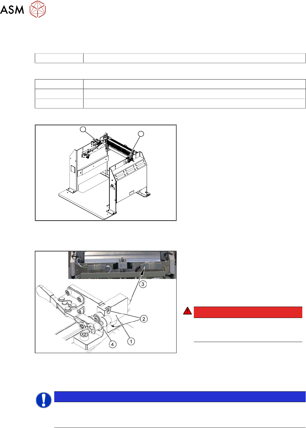
Fig.521: Position end switch left and right
1. Position end switch – on the left side
2. Position end switch – on the right side
Removal
Fig.522: Removing the position end switch
1. Position end switch with connection
cable
2. Two fastening screws
3. Connection cable to connector unit
4. Actuation by locking lever
DANGER!
Switch off the voltage supply
Press the ON/OFF button to switch off
and then unplug the power supply.
.
► Remove the two screws fastening the limit switch.
► Open the casing of the connector at the back and label the terminal connections.
NOTICE
Connector for left and right position end switch
► The connection cables for the left and right position end switch are connected to a
common connector.
► Disconnect the connection cable for the relevant position end switch, in the connector.
► Unthread the connection cable and remove the position end switch.
9 Component feeding
9.4 Docking Station for Component Trolley
Service Manual SIPLACE X-Serie S 06/2019 387
Installation
► Loosely screw in the new position end switch.
► Run the connection cable to the connector.
► Reconnect the connection cable and close the connector casing.
► Align the position end switch so that the locking lever actuator switches properly.
► Tighten the fastening screws.
► Connect the power pack connection cable and press the ON/OFF button to switch on.
► Check the position end switch function by trying out the locking procedure.
9.4.7 Replacing the 40-fold feeder unlocking device
Parts
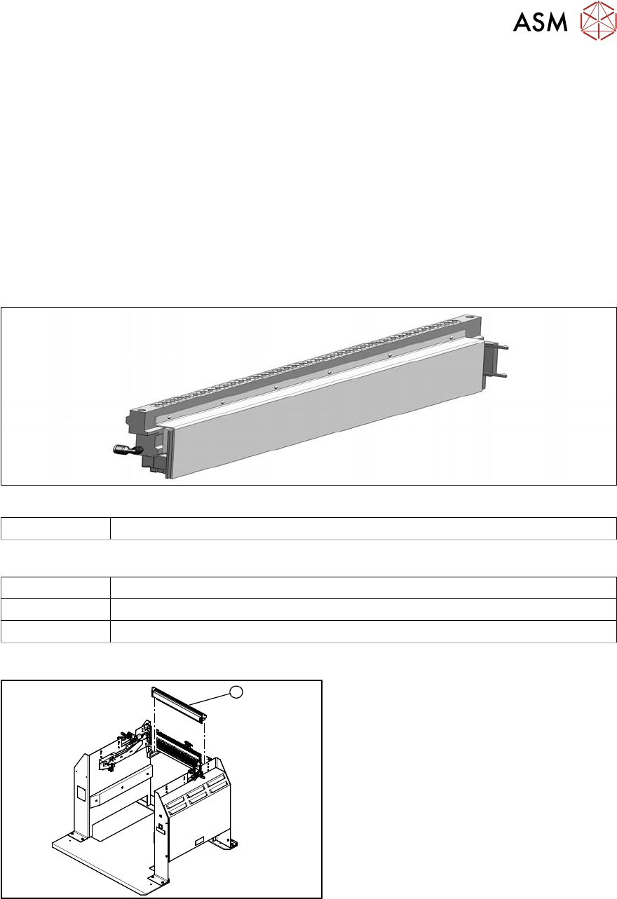
Fig.523: 40 fold feeder unlocking device
03011582-xx 40 fold feeder unlocking device
Equipment and tools
00353832-xx Allen key set
Wire cutters
Cable ties
Overview
1
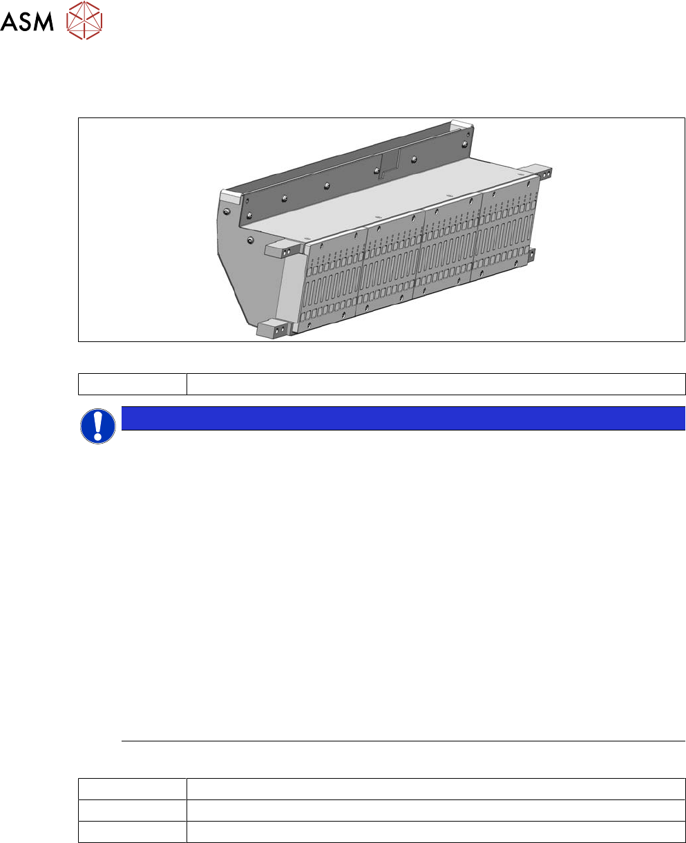
Fig.524: Feeder unlocking device on docking station
1. 40 fold feeder unlocking device
Removal / installation
The 40-fold feeder unlocking device is the same assembly used in the COTi. The service work is
identical with the procedure used for the COTi. All necessary service work is described there.
See also
2 9.2.5 "Replacing the 40-fold feeder unlock device" [}362]
9 Component feeding
9.4 Docking Station for Component Trolley
388 Service Manual SIPLACE X-Serie S 06/2019
9.4.8 Replacing the Feeder Control Unit (FCU)
Parts
Fig.525: FCU
03059623Sxx X-FCU/ X-Series (replaces: [03020068-xx])
NOTICE
Observing the technical information
Observe the technical information "Replacing the FCU" (SIPLACE X-Series, SX4/DX4,
X‑SeriesS, Docking Station) [DE: TI2014-11D15] [EN: TI2014-11E15]:
Since June 2010, the "nozzle changer control" and the "cutter control" have been integrated
into the "X-FCU / SIPLACE X-Series" [03059623-xx]. The CAN nodes are therefore no
longer used.
The assembly is, however, not 100% downwards compatible with regard to the mechanical
installation.
► Docking station for component trolley SIPLACE [00116933‑xx] (SIPLACE X-
Series)
Any remaining old "FCU SIPLACE X-Series" [03020068‑xx] should be used for the
docking station for SIPLACE X‑Series component trolleys [00116933‑xx] and for spare
part disposal at these docking stations.
In order to use the new "X‑FCU SIPLACE X-Series" [03059623Sxx] on the "docking
station X [00116933‑xx]", you need to use an additional "cable set X-FCU for docking
station X [00116933‑xx]" [03098897‑xx].
Since March 2013, all new deliveries of the docking station for SIPLACE X-Series
have the new FCU.
Equipment and tools
00353832-xx Allen key set
Wire cutters
Cable ties