00197042-04_SM_X-Serie-S_Customer_EN.pdf - 第40页
2 Basic Machine 2.7 Replacing Stationary Component Camera Digital Type 25/33/36 40 Service Manual SIPLACE X-Serie S 06/2019 2.7.3 PCBs Stationary Cameras 2.7.3.1 Vision LED driver VLT 33 This board is part of the station…

2 Basic Machine
2.7 Replacing Stationary Component Camera Digital Type 25/33/36
Service Manual SIPLACE X-Serie S 06/2019 39
2.7.2 Troubleshooting Stationary Cameras
Error / problem
●
Errors arise during nozzle scanning, even though the nozzle has already been checked to en-
sure that it is clean.
●
During camera verification (FCCS), it is difficult to achieve the necessary illumination.
●
Increased component rejection rate, particularly with low-contrast components.
Cause
If one or more of these errors occurs, the cause may be a dirty camera.
Solution
► Clean the stationary cameras. Please read the technical information [DE: TI2014-10D09] [EN:
TI2014-10E09] for more information.
Problem
●
Error message 37752: "The LED test of the camera illumination failed" at GigE cameras
Solution
► Please contact the SIPLACE service team for more information.
Give them the following reference number: TI2015-08V03.
2 Basic Machine
2.7 Replacing Stationary Component Camera Digital Type 25/33/36
40 Service Manual SIPLACE X-Serie S 06/2019
2.7.3 PCBs Stationary Cameras
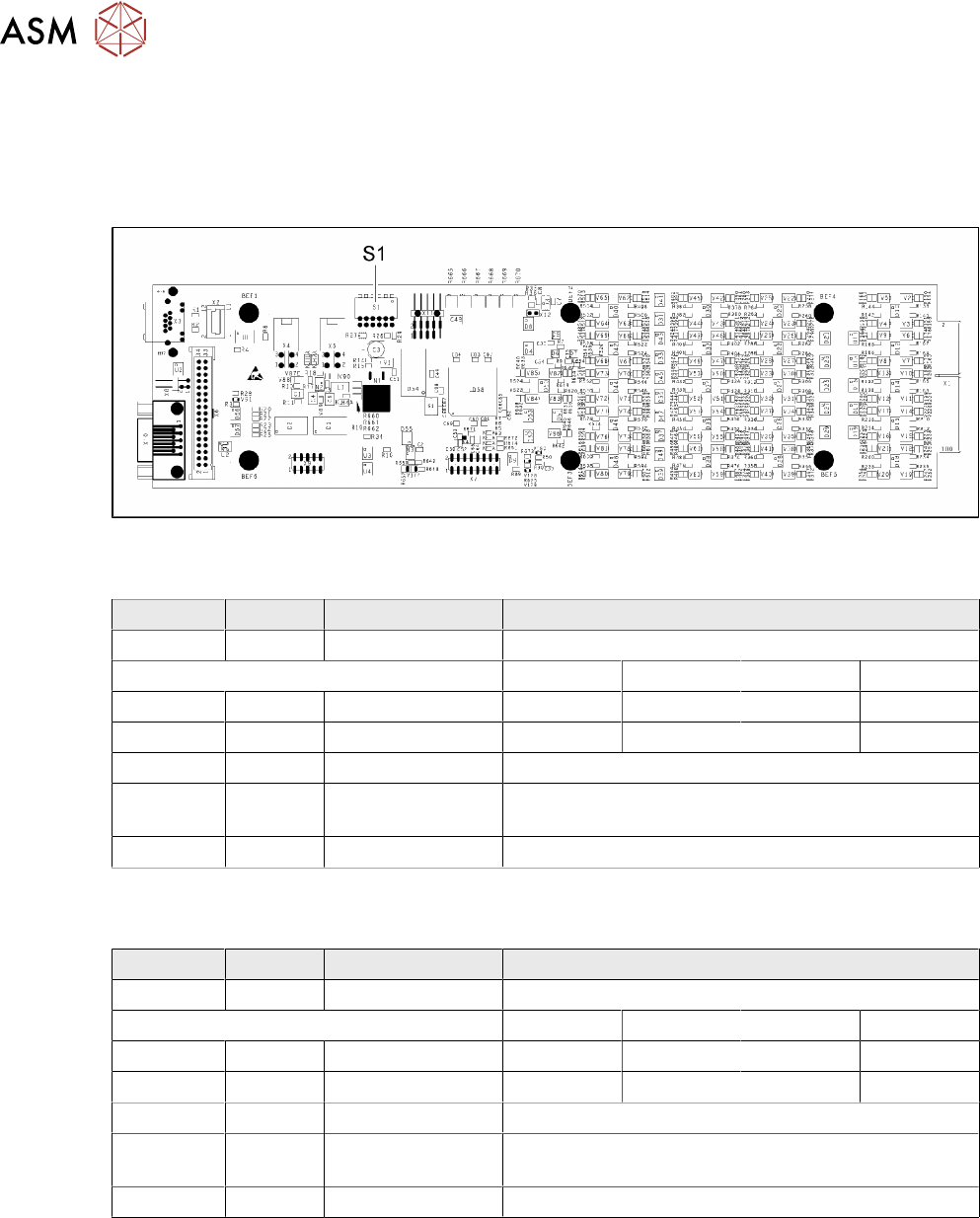
2.7.3.1 Vision LED driver VLT 33
This board is part of the stationary cameras SST25, SST33 and SST36 (without GigE). The station-
ary cameras which can be installed will depend on the machine type.
Fig.29: 03039244-03
DIP switch S1 for SST25 [03039244-03]
Switch Status Signal name Description
S1.1 OFF VCU_CODE OFF: normal operation, ON: Reset
Location 1 Location 2 Location 3 Location 4
S1.2 ON/OFF GANTRY_ID_0 *) OFF ON OFF ON
S1.3 ON/OFF GANTRY_ID_1 *) OFF OFF ON ON
S1.4 OFF SMD_LED OFF: standard LED, ON: SMD LED
S1.5 OFF CAN_H OFF: with CAN terminator
ON: without CAN terminator
S1.6 OFF CAN_GROUP OFF: FC camera, ON: IC camera
*) Set the location at which the stationary camera is fitted.
DIP switch S1 for SST33, 36 [03039244-03]
Switch Status Signal name Description
S1.1 OFF VCU_CODE OFF: normal operation, ON: Reset
Location 1 Location 2 Location 3 Location 4
S1.2 ON/OFF GANTRY_ID_0 *) OFF ON OFF ON
S1.3 ON/OFF GANTRY_ID_1 *) OFF OFF ON ON
S1.4 OFF SMD_LED OFF: standard LED, ON: SMD LED
S1.5 OFF CAN_H OFF: with CAN terminator
ON: without CAN terminator
S1.6 ON CAN_GROUP ON: IC camera , OFF: FC camera
*) Set the location at which the stationary camera is fitted.
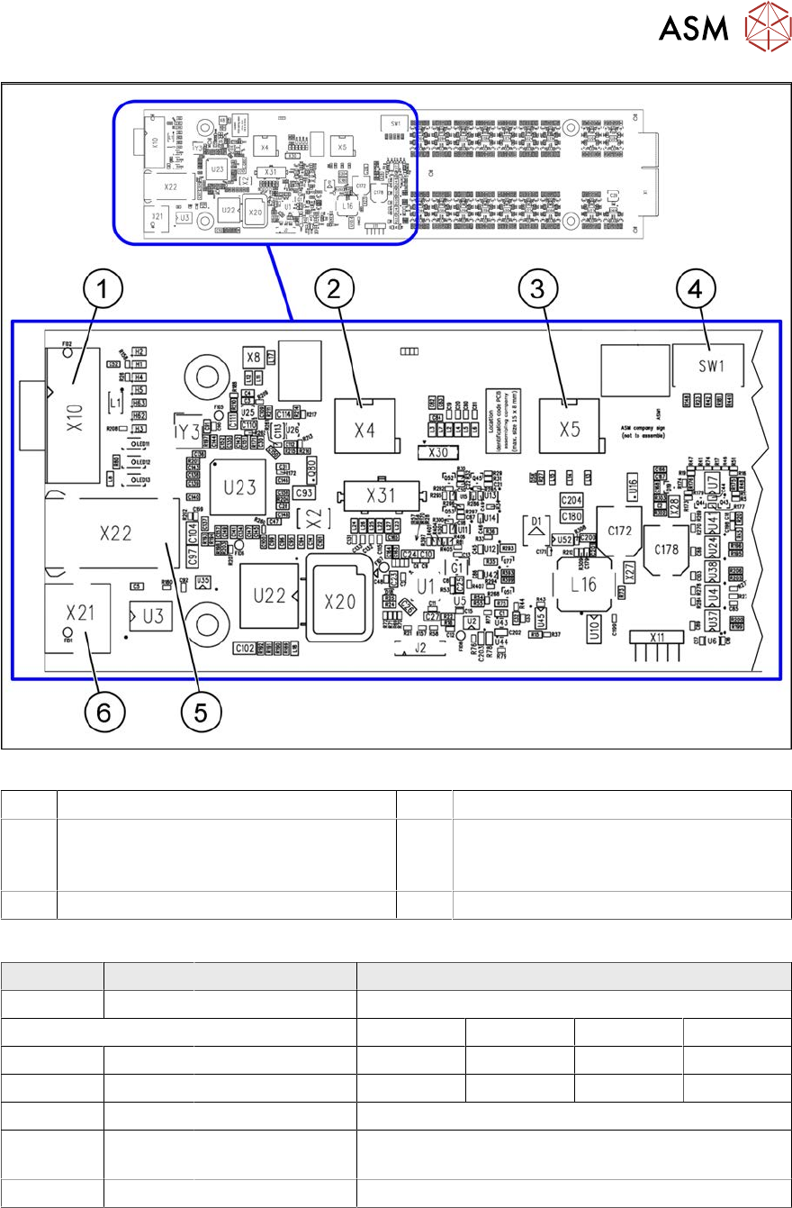
2.7.3.2 Vision LED Controller VLC25/33 GigE DTC
●
Vision LED Controller VLC33 GigE DTC [03117981-xx]
●
Vision LED Controller VLC25 GigE DTC [03117587-xx]
These two circuit boards are in principle identical. The VLC25 board however, also has the con-
nectors X21 and X22
The circuit boards are part of the stationary camera SST25/33 GigE.
2 Basic Machine
2.7 Replacing Stationary Component Camera Digital Type 25/33/36
Service Manual SIPLACE X-Serie S 06/2019 41
Fig.30: Vision LED Controller VLC25 GigE DTC [03117587-xx]
1 CAN bus 2 X4: Cable for power supply
3 X5: Cable for power supply, bridge to FC
camera
(Not used in TX-Series)
4 DIP switch SW1 (see below)
5 Connector X22 (VLC25 only) 6 Connector X21 (VLC25 only)
DIP switch S1 [03117587-xx] [03117981-01]
Switch Status Signal name Description
S1.1 OFF VCU_CODE OFF: normal operation, ON: Reset
Location 1 Location 2 Location 3 Location 4
S1.2 ON/OFF GANTRY_ID_0 *) OFF ON OFF ON
S1.3 ON/OFF GANTRY_ID_1 *) OFF OFF ON ON
S1.4 OFF SMD_LED OFF: standard LED, ON: SMD LED
S1.5 OFF CAN_H OFF: with CAN terminator
ON: without CAN terminator
S1.6 ON/OFF CAN_GROUP ON: IC camera , OFF: FC camera
*) Set the location at which the stationary camera is fitted.