00197042-04_SM_X-Serie-S_Customer_EN.pdf - 第400页
9 Component feeding 9.6 Smart Pin Support 400 Service Manual SIPLACE X-Serie S 06/2019 9.6.2 Replacing the front section of the cylinder Parts, equipment and tools ● Front section of cylinder assembly [03090168Sxx] ● Ass…
9 Component feeding
9.6 Smart Pin Support
Service Manual SIPLACE X-Serie S 06/2019 399
9.6.1 Replacing the Pin Picker Assembly
► For replacing the pin picker, read the Assembly instructions "Smart Pin Support – SIPLACE X-
Series S" [00197394-xx]. Observe the following instructions:
Fig.544: Fastening screws
► Make sure that you note the different
fastening screws for the pin picker.
► When assembling the pin picker, make
sure that you do not damage the
screwdrivers on the screw locks.
► After assembly, check the screw locks
to see whether they are loose. If this is
the case, remove the pin picker and re-
place the screw fastening the screw
lock.
► Make sure that the cables are run correctly.
► Replace any opened cable ties.
► Perform a complete calibration after the installation.
9 Component feeding
9.6 Smart Pin Support
400 Service Manual SIPLACE X-Serie S 06/2019
9.6.2 Replacing the front section of the cylinder
Parts, equipment and tools
●
Front section of cylinder assembly [03090168Sxx]
●
Assembly instructions "Smart Pin Support" for SIPLACE X‑SeriesS [DEEN:00197394‑xx]
Overview
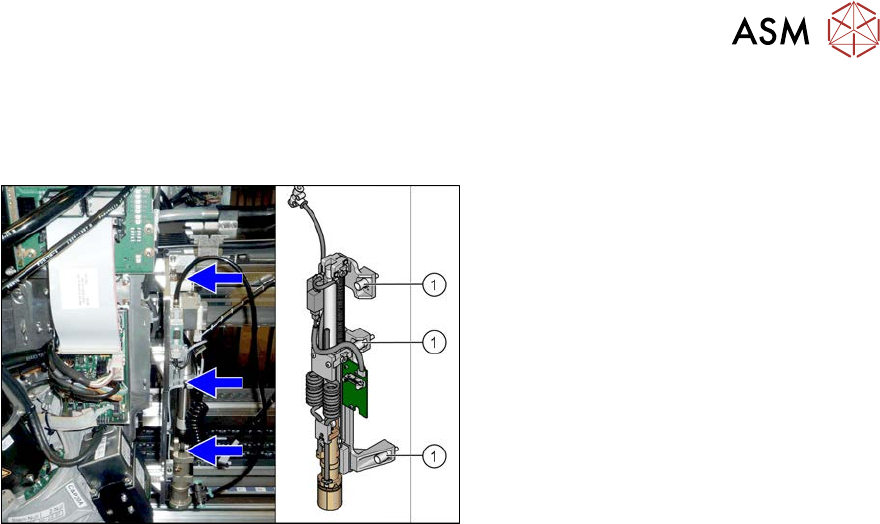
Fig.545: Cylinder
1. Cylinder - front section
2. Cylinder - back section
3. Swivel head
4. Pneumatic connection to the back sec-
tion of the cylinder
5. Tension relief
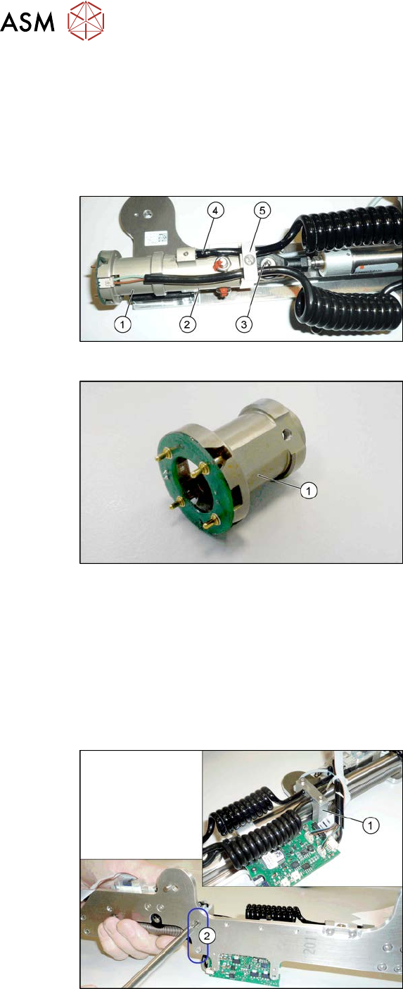
Fig.546: Cylinder - front section
1. Cylinder - front section
Removal
► Switch off the machine, disconnect it from the power supply and secure it to prevent
unauthorized reactivation.
1.2 "Preparatory work..." [}16]
► Remove the pin picker. For more information, read section 9.6.1 "Replacing the Pin Picker
Assembly" [}399].
► Remove the screw fastening the swivel head.
Fig.547: Screws fastening the guide
► Remove the two screws(2) fastening
the pneumatic cylinder guidance(1).
9 Component feeding
9.6 Smart Pin Support
Service Manual SIPLACE X-Serie S 06/2019 401
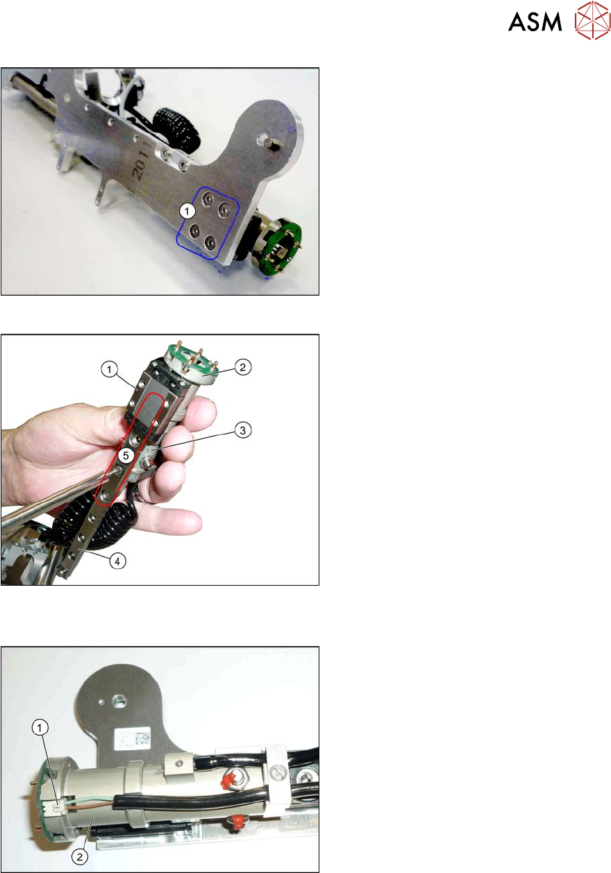
Fig.548: Screws fastening the linear guide
► Remove the fourscrews(1) fastening
the linear guide.
► Remove the linear guide from the base
plate. To do this, unhook the spring
from the top of the linear guide.
Fig.549: Screws fastening the cylinder
1. Trolley on the linear guide
2. Cylinder - front section
3. Cylinder - back section
4. Linear guide
5. Fastening screw for cylinder front and
back sections on the linear guide (par-
tially concealed by the trolley)
► Remove the fastening screws on the front and back sections of the cylinder.
Fig.550: Connector
► Unplug the electrical connection(1) to
the front section of the cylinder(2).
► Remove the front section of the cylin-
der.
Installation
► Follow the removal instructions in reverse order for installation. Also observe the following
instructions:
– When you screw in the linear guide carriage, press it to the left, against the stop edge, so
that it lies flush against the base plate.