00197042-04_SM_X-Serie-S_Customer_EN.pdf - 第413页
9 Component feeding 9.6 Smart Pin Support Service Manual SIPLACE X-Serie S 06/2019 413 9.6.12 Replacing the top sensor Parts, equipment and tools ● Top sensor [03093273Sxx] ● Assembly instructions "Smart Pin Support…
9 Component feeding
9.6 Smart Pin Support
412 Service Manual SIPLACE X-Serie S 06/2019
9.6.11 Replacing the tension spring
Parts, equipment and tools
●
Tension spring (reduced eyelet) [03089675-xx]
●
Circlip pliers size 0 (supplier: http://www.hoffmann-tools.com – item no.:719770 J0)
●
Assembly instructions "Smart Pin Support" for SIPLACE X‑SeriesS [DEEN:00197394‑xx]
Removal
► Switch off the machine, disconnect it from the power supply and secure it to prevent
unauthorized reactivation.
1.2 "Preparatory work..." [}16]
► Remove the pin picker. For more information, read section 9.6.1 "Replacing the Pin Picker
Assembly" [}399].
► Remove the linear guide. For more information, read section 9.6.4 "Replacing the linear
guide" [}403]. You do not need to remove the front and back sections of the cylinder.
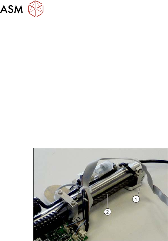
Fig.565: Tension spring
► Loosen the circlip on the holding
bolt(1) of the tension spring(2) and
then pull out the holding bolt.
► Remove the tension spring.
Installation
► Follow the removal instructions in reverse order for installation. Also observe the following
instructions:
– When you screw in the linear guide carriage, press it to the left, against the stop edge, so
that it lies flush against the base plate.
9 Component feeding
9.6 Smart Pin Support
Service Manual SIPLACE X-Serie S 06/2019 413
9.6.12 Replacing the top sensor
Parts, equipment and tools
●
Top sensor [03093273Sxx]
●
Assembly instructions "Smart Pin Support" for SIPLACE X‑SeriesS [DEEN:00197394‑xx]
Overview
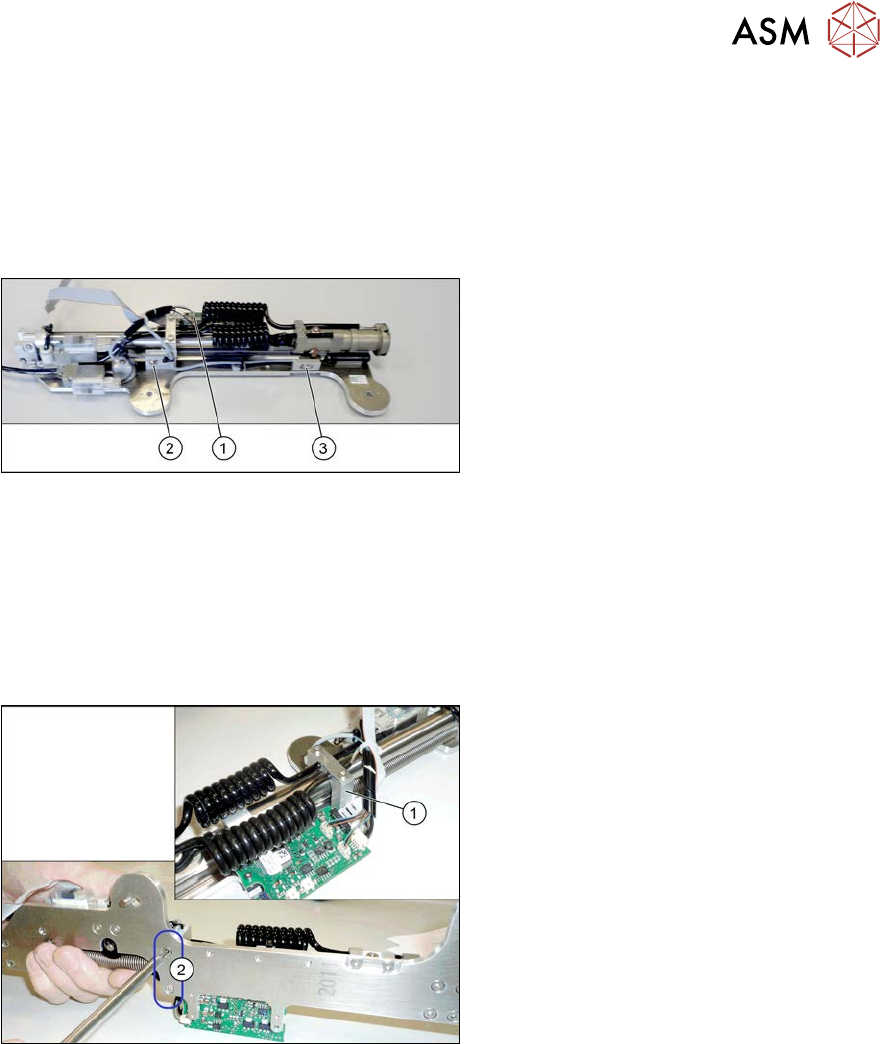
Fig.566: Sensors
1. Control board
2. Fastening screw for top sensor
3. Fastening screw for bottom sensor
Removal
► Switch off the machine, disconnect it from the power supply and secure it to prevent
unauthorized reactivation.
1.2 "Preparatory work..." [}16]
► Remove the pin picker. For more information, read section 9.6.1 "Replacing the Pin Picker
Assembly" [}399].
Fig.567: Screws fastening the guide
► Remove the two screws(2) fastening
the pneumatic cylinder guidance(1).
► Remove the screws holding the sensor.
► Unthread the sensor cable as far as the
board. Open the corresponding cable
ties to help you, if needed.
► Unplug the sensor cable from the
board. You may want to mark the posi-
tion to make clear assignment easier
later on.
Installation
► Follow the removal instructions in reverse order for installation. Also observe the following
instructions:
– Fasten the sensor in the center of the slot.
– Replace any opened cable ties.
9 Component feeding
9.6 Smart Pin Support
414 Service Manual SIPLACE X-Serie S 06/2019
9.6.13 Replacing the bottom sensor
Parts, equipment and tools
●
Inductive sensor assembly, bottom SPS [03090192Sxx]
●
Assembly instructions "Smart Pin Support" for SIPLACE X‑SeriesS [DEEN:00197394‑xx]
Overview
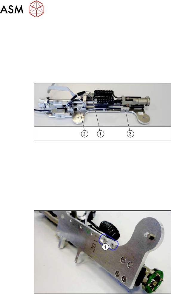
Fig.568: Sensors
1. Control board
2. Fastening screw for top sensor
3. Fastening screw for bottom sensor
Removal
► Switch off the machine, disconnect it from the power supply and secure it to prevent
unauthorized reactivation.
1.2 "Preparatory work..." [}16]
► Remove the pin picker. For more information, read section 9.6.1 "Replacing the Pin Picker
Assembly" [}399].
Fig.569: Screws fastening the sensor mount
► Remove the two screws(1) fastening
the sensor mount.
► Remove the screws holding the sensor.
► Unthread the sensor cable as far as the board. Open the corresponding cable ties to help you,
if needed.
► Unplug the sensor cable from the board. You may want to mark the position to make clear as-
signment easier later on.
Installation
► Follow the removal instructions in reverse order for installation. Also observe the following
instructions:
– Fasten the sensor in the center of the slot.
– Replace any opened cable ties.