00197042-04_SM_X-Serie-S_Customer_EN.pdf - 第42页
2 Basic Machine 2.7 Replacing Stationary Component Camera Digital Type 25/33/36 42 Service Manual SIPLACE X-Serie S 06/2019 2.7.4 DIP Switch for Camera Types 25 and 33 Setting ► Switch off the machine, disconnect it from…
2 Basic Machine
2.7 Replacing Stationary Component Camera Digital Type 25/33/36
Service Manual SIPLACE X-Serie S 06/2019 41
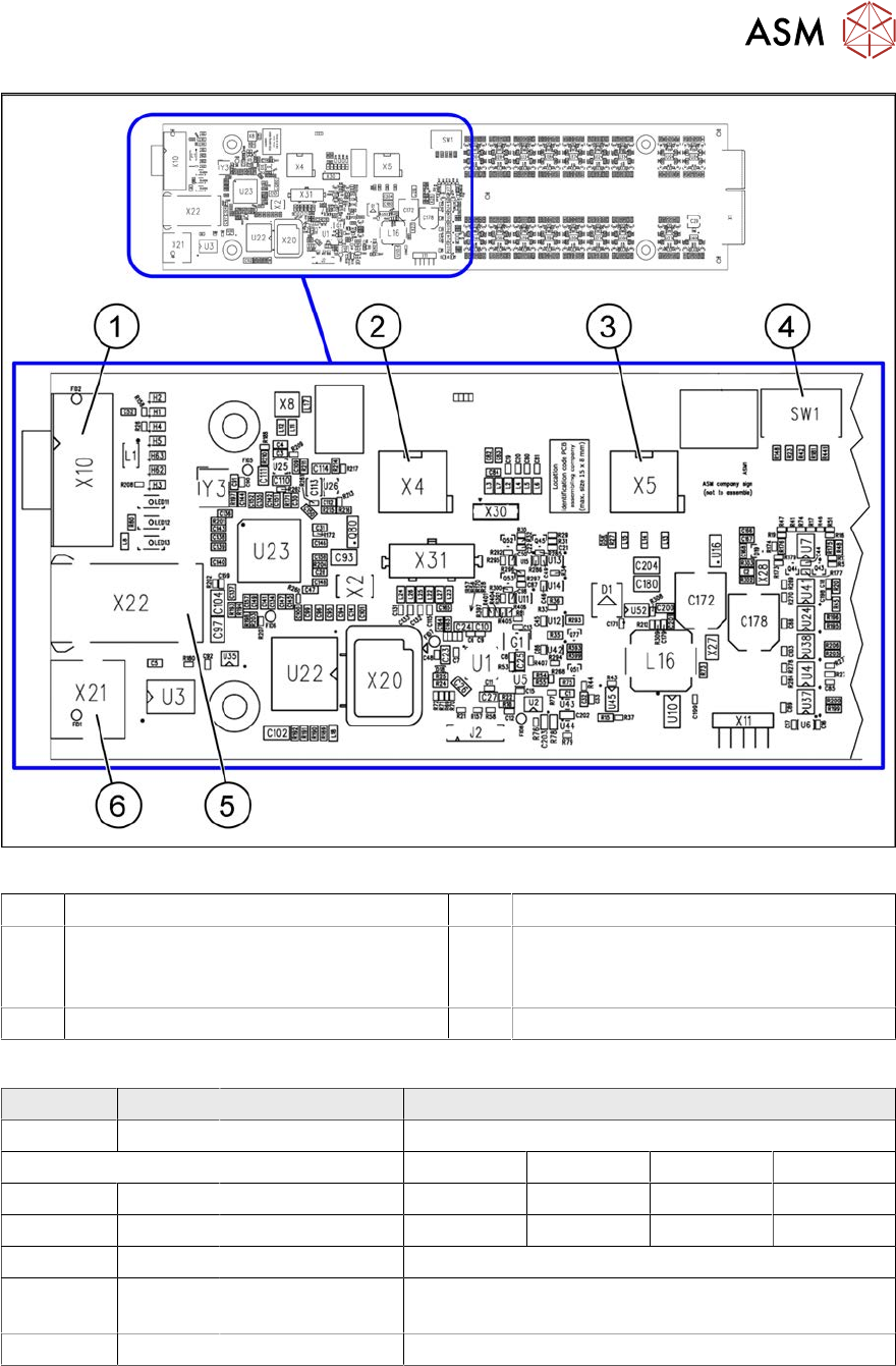
Fig.30: Vision LED Controller VLC25 GigE DTC [03117587-xx]
1 CAN bus 2 X4: Cable for power supply
3 X5: Cable for power supply, bridge to FC
camera
(Not used in TX-Series)
4 DIP switch SW1 (see below)
5 Connector X22 (VLC25 only) 6 Connector X21 (VLC25 only)
DIP switch S1 [03117587-xx] [03117981-01]
Switch Status Signal name Description
S1.1 OFF VCU_CODE OFF: normal operation, ON: Reset
Location 1 Location 2 Location 3 Location 4
S1.2 ON/OFF GANTRY_ID_0 *) OFF ON OFF ON
S1.3 ON/OFF GANTRY_ID_1 *) OFF OFF ON ON
S1.4 OFF SMD_LED OFF: standard LED, ON: SMD LED
S1.5 OFF CAN_H OFF: with CAN terminator
ON: without CAN terminator
S1.6 ON/OFF CAN_GROUP ON: IC camera , OFF: FC camera
*) Set the location at which the stationary camera is fitted.
2 Basic Machine
2.7 Replacing Stationary Component Camera Digital Type 25/33/36
42 Service Manual SIPLACE X-Serie S 06/2019
2.7.4 DIP Switch for Camera Types 25 and 33
Setting
► Switch off the machine, disconnect it from the power supply and secure it to prevent
unauthorized reactivation.
1.2 "Preparatory work..." [}16]
► Remove the camera upper part and the cover on the lower part, to gain access to the DIP
switches.
► Set the DIP switches. (see below).
► Fit all parts by following the above instructions in the reverse order.
DIP switches
Boards with version status 01 and 02 are fitted with a TQ module. In this case, the DIP switching
block is 8 pin.
Boards with version status 03 or higher do not have a TQ module. In this case, the DIP switching
block is 6 pin.
Version state 01 and 02: DIP switch settings (8 pin)
S Setting for gantry* Comments
1 2
1 OFF OFF Bootstrap
2 OFF OFF Reset
3 OFF OFF Gantry ID 0
4 OFF ON Gantry ID 1
5 OFF OFF Test
6 OFF OFF CAN terminator
7 ON ON CAN speed: ON: 1 Mbit/s, OFF: 500 KB/s
8 x x x x OFF: FC camera (type 25), ON: IC camera (type
33)
* Not all gantries may be available, depending on the machine type.
Version state 03 and higher: DIP switch settings (6 pin)
S Setting for gantry* Comments
1 2
1 OFF OFF Reset
2 OFF OFF Gantry ID 0
3 OFF ON Gantry ID 1
4 x x x x LED: This switch is delivered with a fixed preset-
ting. Do not change this setting!
5 OFF OFF CAN terminator
6 x x x x OFF: FC camera (type 25), ON: IC camera (type
33)
* Not all gantries may be available, depending on the machine type.
See also
2 2.7.3.1 "Vision LED driver VLT 33" [}40]
2 Basic Machine
2.8 Nozzle Changers and Reject Boxes
Service Manual SIPLACE X-Serie S 06/2019 43
2.8 Nozzle Changers and Reject Boxes
See also
2 9.2 "COT insert" [}355]
2.8.1 Nozzle Changers and Nozzle Stations - Overview
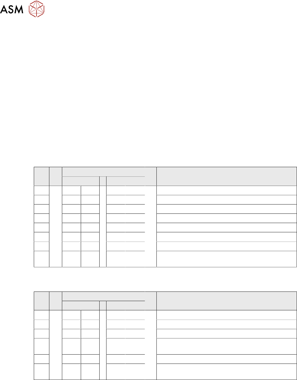
Fig.31: Nozzle changer short [03103649‑xx]
Standard nozzle changer, short
[03103649‑xx] for four magazines
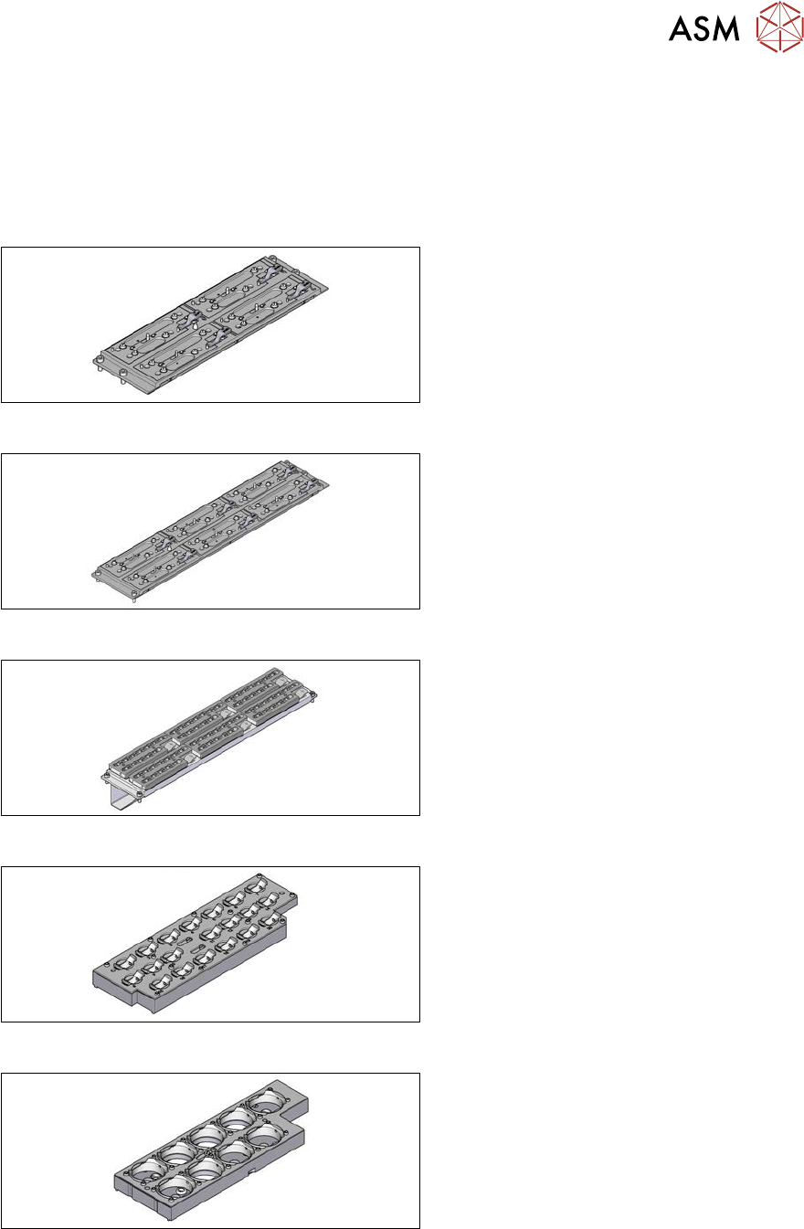
Fig.32: Nozzle changer, long [03147324‑xx]
Standard nozzle changer, long
[03147324‑xx] for six magazines
Fig.33: Nozzle changer, long
Nozzle changer, long
for SIPLACE C&P20 [03070123‑xx]
for SIPLACE C&P20M [03147324‑xx]
with six magazines [00119715‑xx]
Fig.34: Magazine 20xx [03066107-xx]
Magazine for nozzles of 20 xx series
Fig.35: Magazine 28xx [03065782-xx]
Magazine for nozzles of 28 xx series