00197042-04_SM_X-Serie-S_Customer_EN.pdf - 第421页
10 Vacuum Pump 10.1 Replacing the vacuum pump Service Manual SIPLACE X-Serie S 06/2019 421 10 Vacuum Pump DANGER Observe User Manual ► Please observe the safety instructions in the user manual for all work! 10.1 Replacin…
9 Component feeding
9.6 Smart Pin Support
420 Service Manual SIPLACE X-Serie S 06/2019
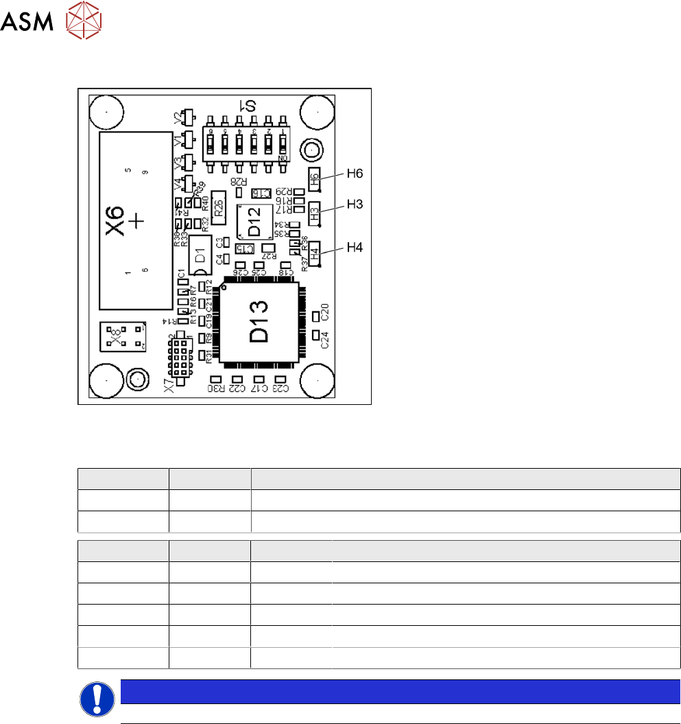
9.6.18.1 Magazine recognition board
Fig.577: Magazine recognition board [03093494-xx]
The magazine recognition board is part of the
pin magazines for the "Smart Pin Support" op-
tion.
This board may be missing, depending on the
magazine version used.
LEDs:
H3: not used
H4: FPGA OK
H6: Power supply 3.3 V OK
DIP switch S1 - jumper assignment
S1.1 S1.2 Magazine connected at:
ON OFF NC connection 2
OFF ON NC connection 4
S1.4 S1.5 S1.6 Meaning
OFF OFF OFF Garage is switched off
ON OFF OFF Garage type W5
OFF ON OFF Garage type Q10
ON ON OFF Garage type L10
X X ON Reserved
NOTICE
Jumper S1.3 is not used.
10 Vacuum Pump
10.1 Replacing the vacuum pump
Service Manual SIPLACE X-Serie S 06/2019 421
10 Vacuum Pump
DANGER
Observe User Manual
► Please observe the safety instructions in the user manual for all work!
10.1 Replacing the vacuum pump
Parts, equipment and tools
●
Vacuum pump Becker VX4 25 [03069679-xx]
You will also need the relevant assembly instruction manual for your machine:
●
Assembly instructions "Option Vacuum Pump SIPLACE X-Series S up to Gxxxx, SX4/
DX4" [DE+EN:00196845‑xx]
●
Assembly instructions "Option Vacuum Pump SIPLACE X-Series S from Hxxxx " [DEEN:
00198599‑xx]
Removal/installation
► Refer to the appropriate assembly instructions.
10.2 Replacing the exhaust air hose
Parts, equipment and tools
●
Exhaust air hose ID100 [03087599-xx]
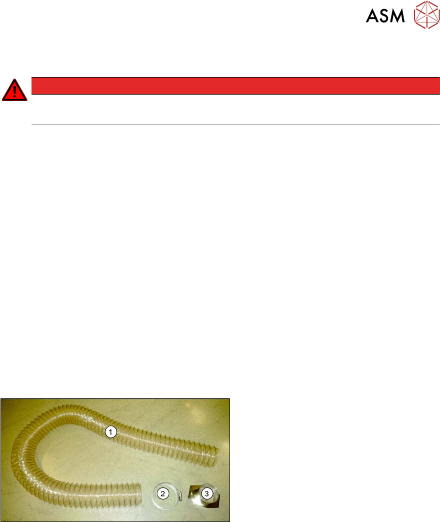
Overview
Fig.578: Exhaust air hose
1. Exhaust air hose
2. Hose clamp
3. Hose holder
The exhaust tube is fixed to the underside of
the machine.
Removal
► Switch off the machine, disconnect it from the power supply and secure it to prevent
unauthorized reactivation.
1.2 "Preparatory work..." [}16]
► Loosen the two screws fastening the hose holder. The hose holder has two keyholes. The
fastening screws do not need to be completely loosened.
► Turn the hose holder a little and remove it.
► Open the hose clamp and remove the hose.
Installation
► Follow the removal instructions in reverse order for installation.
10 Vacuum Pump
10.3 Replacing the connector unit box
422 Service Manual SIPLACE X-Serie S 06/2019
10.3 Replacing the connector unit box
Parts, equipment and tools
●
Vacuum pump connector unit box [03079448-xx]
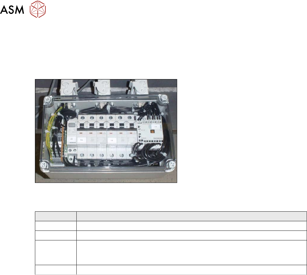
Overview
Fig.579: Connector unit box
The connector unit box is located at the bot-
tom of the machine frame, at location 2.
Connection on the connector unit box
Terminal Description
X2qr Voltage
X3qr Control
X4qr, X5qr Pumps (sequence not important)
If only one pump is installed, the second connection must be closed with a bridge
connector.
X6qr Fan
Removal
► Switch off the machine, disconnect it from the power supply and secure it to prevent
unauthorized reactivation.
1.2 "Preparatory work..." [}16]
► Dismantle the waste slide for better access. (see 9.1.2 "Replacing the waste tape
slide" [}328]).
► Unplug all electrical connections from the connector unit box. If necessary, mark their posi-
tions to make clear assignment easier later on.
► Take the connector unit box out of the machine.
Installation
► Follow the removal instructions in reverse order for installation. Also observe the following
instructions:
– If not present, the suppressor module must be removed from the old connector unit box
and fitted in the new one (see also 10.5 "Replacing the suppressor module in the con-
nector unit box" [}424]).