00197042-04_SM_X-Serie-S_Customer_EN.pdf - 第423页
10 Vacuum Pump 10.4 Replacing the power supply cable for the vacuum pump Service Manual SIPLACE X-Serie S 06/2019 423 10.4 Replacing the power supply cable for the vacuum pump Parts, equipment and tools ● Cable: power su…
10 Vacuum Pump
10.3 Replacing the connector unit box
422 Service Manual SIPLACE X-Serie S 06/2019
10.3 Replacing the connector unit box
Parts, equipment and tools
●
Vacuum pump connector unit box [03079448-xx]
Overview
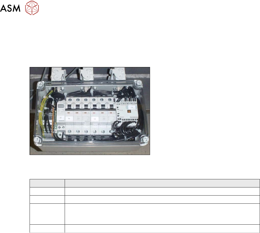
Fig.579: Connector unit box
The connector unit box is located at the bot-
tom of the machine frame, at location 2.
Connection on the connector unit box
Terminal Description
X2qr Voltage
X3qr Control
X4qr, X5qr Pumps (sequence not important)
If only one pump is installed, the second connection must be closed with a bridge
connector.
X6qr Fan
Removal
► Switch off the machine, disconnect it from the power supply and secure it to prevent
unauthorized reactivation.
1.2 "Preparatory work..." [}16]
► Dismantle the waste slide for better access. (see 9.1.2 "Replacing the waste tape
slide" [}328]).
► Unplug all electrical connections from the connector unit box. If necessary, mark their posi-
tions to make clear assignment easier later on.
► Take the connector unit box out of the machine.
Installation
► Follow the removal instructions in reverse order for installation. Also observe the following
instructions:
– If not present, the suppressor module must be removed from the old connector unit box
and fitted in the new one (see also 10.5 "Replacing the suppressor module in the con-
nector unit box" [}424]).
10 Vacuum Pump
10.4 Replacing the power supply cable for the vacuum pump
Service Manual SIPLACE X-Serie S 06/2019 423
10.4 Replacing the power supply cable for the vacuum pump
Parts, equipment and tools
●
Cable: power supply for vacuum pump [03079997-xx]
You will also need the relevant assembly instruction manual for your machine:
●
Assembly instructions "Option Vacuum Pump SIPLACE X-Series S up to Gxxxx, SX4/
DX4" [DE+EN:00196845‑xx]
●
Assembly instructions "Option Vacuum Pump SIPLACE X-Series S from Hxxxx " [DEEN:
00198599‑xx]
Overview
Fig.580: Connector unit box
The power supply cable for the vacuum
pump leads from the connector unit box to
the vacuum pump.
The connector unit box is located at the bot-
tom of the machine frame, at location 2.
Connection on the connector unit box
Terminal Description
X2qr Voltage
X3qr Control
X4qr, X5qr Pumps (sequence not important)
If only one pump is installed, the second connection must be closed with a bridge
connector.
X6qr Fan
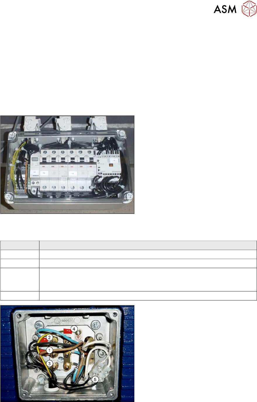
Fig.581: Cable connections on the vacuum pump
1. Conductor (1) to connection V1
2. Conductor (2) to connection U1
3. Conductor (3) to connection W1
4. Protective ground at connection (4)
5. Black cable (temperature monitor) on
the luster terminal(5)
Removal/installation
► Refer to the appropriate assembly instructions.
10 Vacuum Pump
10.5 Replacing the suppressor module in the connector unit box
424 Service Manual SIPLACE X-Serie S 06/2019
10.5 Replacing the suppressor module in the connector unit
box
Parts, equipment and tools
●
EMC suppressor module RC 3x400V 575VAC 4kW [03097216-xx]
Overview
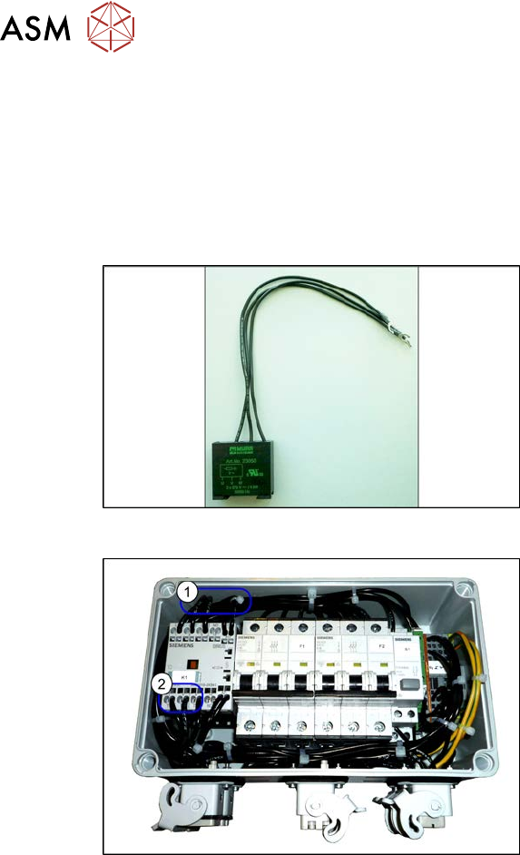
Fig.582: Suppression module
Suppression module
Fig.583: Connector unit box
1. Installation point of suppression module
2. The suppression module is connected
to terminal 2, 4 and 6.
Removal
The suppressor module is fitted in the connector unit box. The connector unit box is located at the
bottom of the machine frame, at location 2.
► For more information, read section 10.3 "Replacing the connector unit box" [}422].
Installation
► Observe the following instructions during installation:
– Cut off the cable lugs and remove approx. 1 cm of insulation from the end of the cable.
– Unlock the terminals (e.g. with a screwdriver) and insert one cable each into terminals 2, 4
and6.