00197042-04_SM_X-Serie-S_Customer_EN.pdf - 第47页
2 Basic Machine 2.8 Nozzle Changers and Reject Boxes Service Manual SIPLACE X-Serie S 06/2019 47 2.8.4 Setting the Nozzle Changer Height Parts, equipment and tools ● Measuring scale ● NC shim plate [03021079-xx] Overview…
2 Basic Machine
2.8 Nozzle Changers and Reject Boxes
46 Service Manual SIPLACE X-Serie S 06/2019
2.8.3 Setting the Nozzle Reject and Station Height
Parts, equipment and tools
●
Depth measuring gauge (300mm) [03079617-xx]
●
Shim plates for nozzle reject device [03039514-xx]
●
Screws DIN 7991-M4 x 20-8.8 [00333782-xx]
●
Plastic sheet (to keep the depth measuring gauge away from the magnets)
Setting
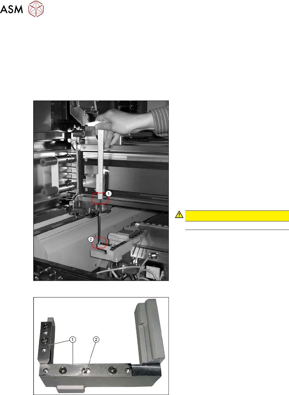
Fig.40: Measurement
1. Position upper edge of measuring scale
on the linear guidance
2. Bottom end of measuring gauge on the
assembly surface of the nozzle station
► Push the placement head to be meas-
ured outwards.
► Place a plastic plate in front of the mag-
nets.
► Position the measuring gauge on the
upper edge of the nozzle station
assembly surface and measure the dis-
tance to the upper edge of the lower X
axis linear guidance.
CAUTION!
Hold the measuring scale vertically!
.
Fig.41: Shim plates
1. Shim plates
2. Slot
► Set a distance of 139.0±0.2mm for all
placement heads.
If the distance is too large, insert shim
plates:
shim plates for nozzle stripping
device[03039514‑xx],
screws DIN7991 M4x20 - 8.8
[00333782‑xx]
2 Basic Machine
2.8 Nozzle Changers and Reject Boxes
Service Manual SIPLACE X-Serie S 06/2019 47
2.8.4 Setting the Nozzle Changer Height
Parts, equipment and tools
●
Measuring scale
●
NC shim plate [03021079-xx]
Overview
5
1
4
3
2
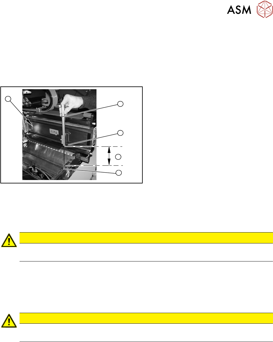
Fig.42: Overview of measurement procedure
1. Measuring scale
2. Top edge of the X axis lower linear
guide
3. Values to be set (150 +/- 0.2 mm)
4. Nozzle changer contact surface
Setting
► During the following inside measurement make sure that the tip of the measuring scale does
not touch the magnetic strip as this might scratch it!
CAUTION
Strong magnetic forces
Place a suitable plastic plate between the magnet and measuring scale.
► Position the measuring scale (1) on the top edge of the X axis lower linear guide (2) and
measure the distance to the nozzle changer contact surface (4).
► Hold the measuring scale vertically (1).
► The setting value (4) is 150+/‑0.2mm
.You can adjust the height, where necessary, by removing or adding NC shim plates.
CAUTION
Crash hazard!
Do not place too many shim plates underneath.
► Repeat this measurement on the inside of the gantry (5).
► Calibrate the position of the nozzle changer.
2 Basic Machine
2.8 Nozzle Changers and Reject Boxes
48 Service Manual SIPLACE X-Serie S 06/2019
2.8.5 Jumpers on the Nozzle Changer
Overview
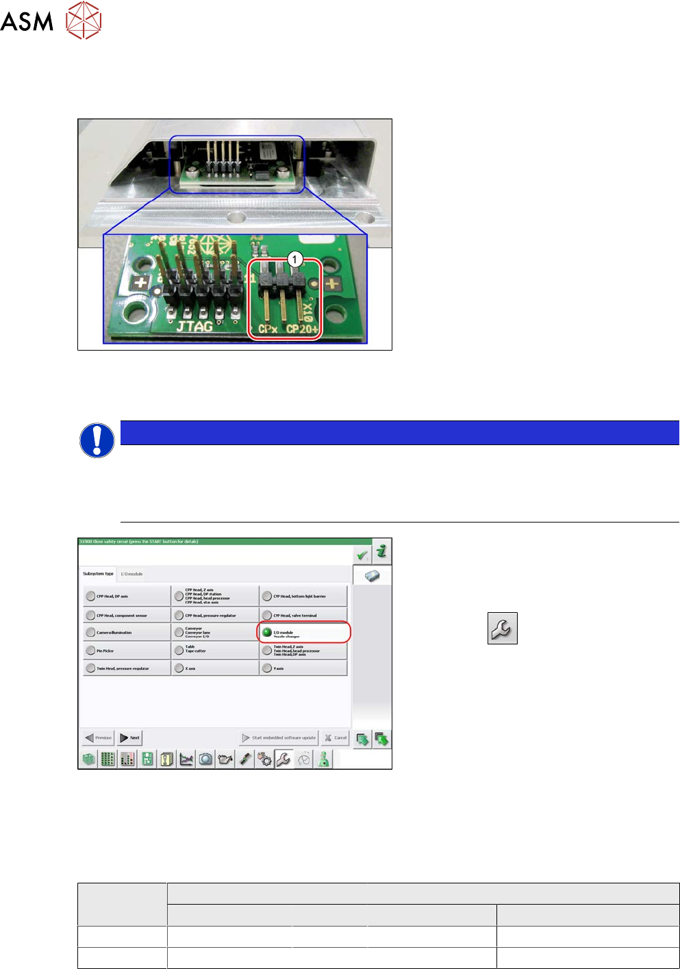
Fig.43: Jumpers on the nozzle changer
1. Jumper X10
The jumper X10 needs to be set at the fol-
lowing nozzle changers:
●
Nozzle changer basic structure CPx/all
assembly - short [03103649-xx]
●
Nozzle changer basic structure CPx/all
assembly - long [03147324-xx]
●
Nozzle changer basic structure CPx/all
assembly - long [03103514-xx]
(replaces: [03103514-xx])
Preparation
NOTICE
Before installation
Due to the design, this setting must be performed before installation in the machine.
► If the new nozzle changer is being fitted as a spare part in a machine with I/O module
control, you will need to reconnect the jumper to pin 1-2.
Fig.44: Checking the I/A module control
To check whether the machine has I/O mod-
ule control, proceed as follows:
► Switch over to the operator level Ser-
vice.
► Click the
button.
► Click on the Embedded software but-
ton.
► Click the Update subsystem button.
► If an I/O module control is present, you
will see the entry Nozzle Changer at I/
O Module.
Setting
► Set the correct value on the jumper for your head type, software and control method.
Jumper X10
Head SW <= 706.x SW >= 707.x
I/O controller XFCU I/O controller XFCU
CPx, DLM 1-2 1-2 1-2 2-3
C&P20P --- --- --- 2-3 (factory settings)