00197042-04_SM_X-Serie-S_Customer_EN.pdf - 第48页
2 Basic Machine 2.8 Nozzle Changers and Reject Boxes 48 Service Manual SIPLACE X-Serie S 06/2019 2.8.5 Jumpers on the Nozzle Changer Overview Fig.43: Jumpers on the nozzle changer 1. Jumper X10 The jumper X10 needs to b…
2 Basic Machine
2.8 Nozzle Changers and Reject Boxes
Service Manual SIPLACE X-Serie S 06/2019 47
2.8.4 Setting the Nozzle Changer Height
Parts, equipment and tools
●
Measuring scale
●
NC shim plate [03021079-xx]
Overview
5
1
4
3
2
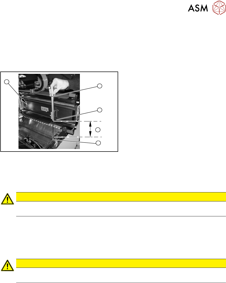
Fig.42: Overview of measurement procedure
1. Measuring scale
2. Top edge of the X axis lower linear
guide
3. Values to be set (150 +/- 0.2 mm)
4. Nozzle changer contact surface
Setting
► During the following inside measurement make sure that the tip of the measuring scale does
not touch the magnetic strip as this might scratch it!
CAUTION
Strong magnetic forces
Place a suitable plastic plate between the magnet and measuring scale.
► Position the measuring scale (1) on the top edge of the X axis lower linear guide (2) and
measure the distance to the nozzle changer contact surface (4).
► Hold the measuring scale vertically (1).
► The setting value (4) is 150+/‑0.2mm
.You can adjust the height, where necessary, by removing or adding NC shim plates.
CAUTION
Crash hazard!
Do not place too many shim plates underneath.
► Repeat this measurement on the inside of the gantry (5).
► Calibrate the position of the nozzle changer.
2 Basic Machine
2.8 Nozzle Changers and Reject Boxes
48 Service Manual SIPLACE X-Serie S 06/2019
2.8.5 Jumpers on the Nozzle Changer
Overview
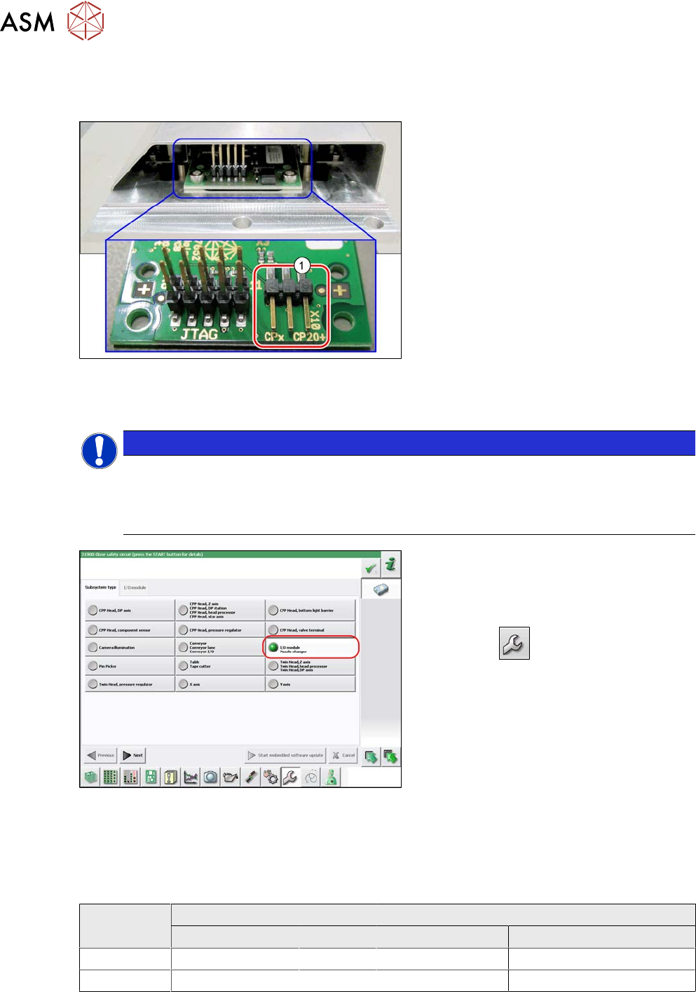
Fig.43: Jumpers on the nozzle changer
1. Jumper X10
The jumper X10 needs to be set at the fol-
lowing nozzle changers:
●
Nozzle changer basic structure CPx/all
assembly - short [03103649-xx]
●
Nozzle changer basic structure CPx/all
assembly - long [03147324-xx]
●
Nozzle changer basic structure CPx/all
assembly - long [03103514-xx]
(replaces: [03103514-xx])
Preparation
NOTICE
Before installation
Due to the design, this setting must be performed before installation in the machine.
► If the new nozzle changer is being fitted as a spare part in a machine with I/O module
control, you will need to reconnect the jumper to pin 1-2.
Fig.44: Checking the I/A module control
To check whether the machine has I/O mod-
ule control, proceed as follows:
► Switch over to the operator level Ser-
vice.
► Click the
button.
► Click on the Embedded software but-
ton.
► Click the Update subsystem button.
► If an I/O module control is present, you
will see the entry Nozzle Changer at I/
O Module.
Setting
► Set the correct value on the jumper for your head type, software and control method.
Jumper X10
Head SW <= 706.x SW >= 707.x
I/O controller XFCU I/O controller XFCU
CPx, DLM 1-2 1-2 1-2 2-3
C&P20P --- --- --- 2-3 (factory settings)
3 Power supply
3.1 Electrical System
Service Manual SIPLACE X-Serie S 06/2019 49
3 Power supply
DANGER
Observe User Manual
► Please observe the safety instructions in the user manual for all work!
3.1 Electrical System
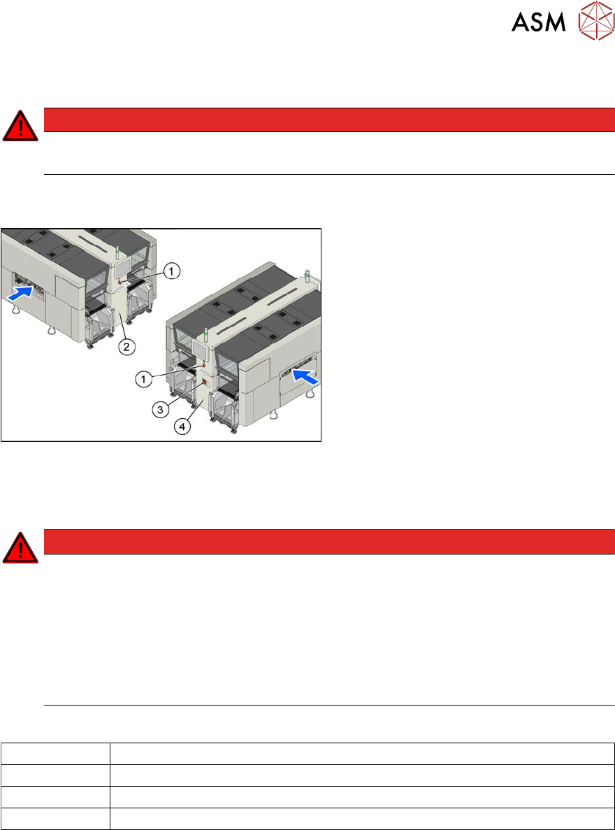
Fig.45: Electrics (example of X4i S shown)
1. EMERGENCY STOP button
2. HCU, GCU, BoxPC
(behind the cover)
3. Main switch
4. Power supply (behind the cover)
3.2 Electrical Checks
DANGER
Observe the safety instructions
There is a risk of dangerous touch voltages and short circuits occurring in power supplies
which have been made accessible and are connected for measurement purposes.
Nonobservance of these safety instructions may cause injury to personnel and dam-
age to the machine!
Measurements may only be performed by specially trained service technicians with appro-
priate qualifications and expertise.
► Observe the safety instructions in this manual and in the instruction manual.
Equipment and tools
00096290-xx Fork wrench set
DUSPOL voltage tester
Digital voltmeter, class 1,5
Test cable with test probes or terminals