00197042-04_SM_X-Serie-S_Customer_EN.pdf - 第51页
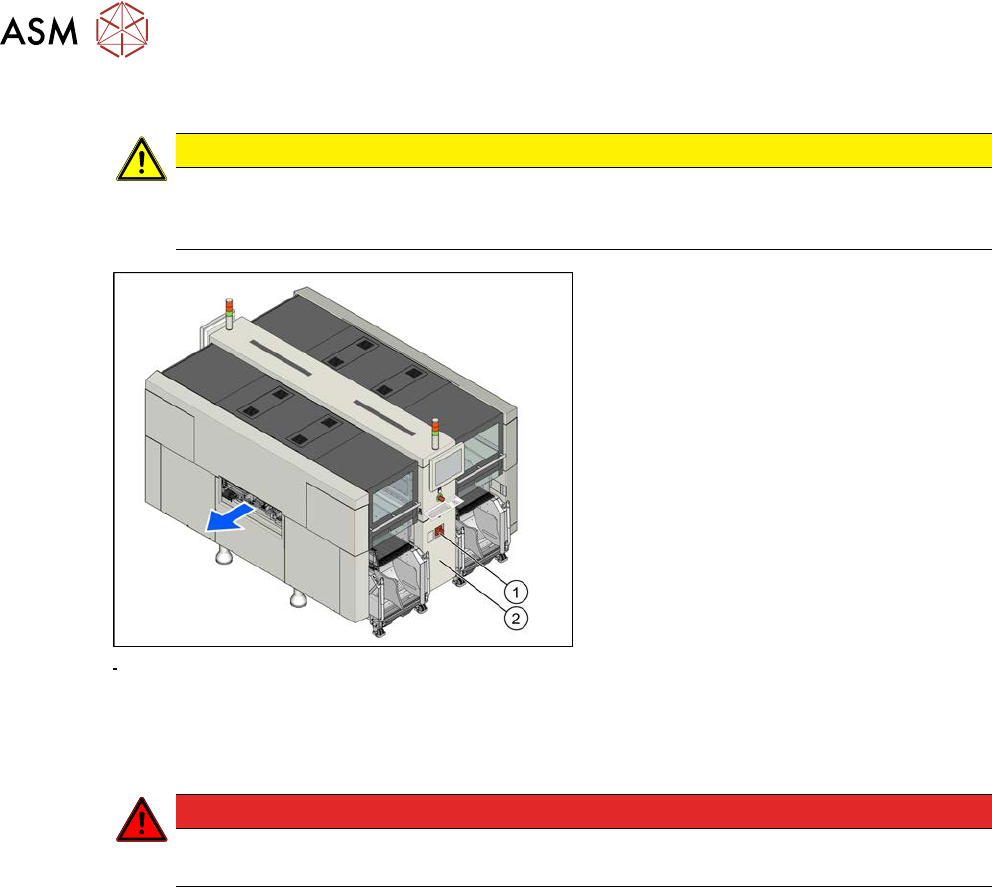
3 Power supply 3.3 Pulling out the Power Supply Service Manual SIPLACE X-Serie S 06/2019 51 3.3 Pulling out the Power Supply CAUTION Risk of tipping If you pull out the power supply completely, there is a risk of tipping…
3 Power supply
3.2 Electrical Checks
50 Service Manual SIPLACE X-Serie S 06/2019
Preparation
CAUTION
Take care not to damage the supply lines!
Make sure that the main power cable and supply cables in the machine are not trapped and
that the insulation is not damaged.
Fig.46: Main switch
► End all placement operations and
switch the machine off at the main
switch(1).
► Disconnect the machine from the main
power supply.
► Open the lock on the power supply
cover(2).
► Remove the power supply fastening screw and pull out the power supply.
► Reconnect the machine to the power supply.
DANGER
Touch voltages
Careful: there may be dangerous touch voltages in the vicinity of the open power supply!
► Switch the machine on again at the main switch and start it up.
Voltages
► Measure the required voltages.
Please refer to the relevant circuit diagram for your machine for details of the various voltages.
●
Detailed circuit diagrams folder for SIPLACE X-Series S (up to Gxxxx) [DE+EN:00197021‑xx]
●
Detailed circuit diagrams folder for SIPLACE X-Series S (from Hxxxx) [DE+EN:00197920‑xx]
3 Power supply
3.3 Pulling out the Power Supply
Service Manual SIPLACE X-Serie S 06/2019 51
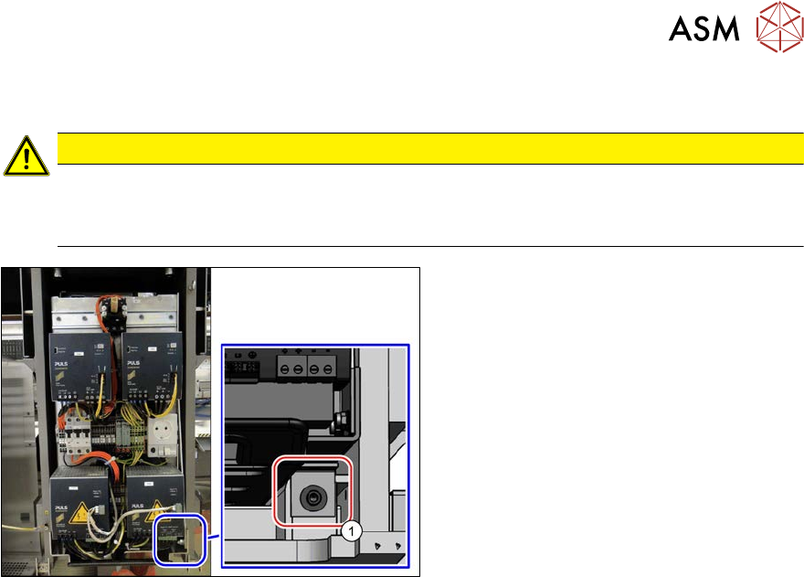
3.3 Pulling out the Power Supply
CAUTION
Risk of tipping
If you pull out the power supply completely, there is a risk of tipping.
► Support the power supply from below.
Fig.47: Screw fastening the power supply
For some service tasks it is necessary to pull
the power supply out of the machine.
► Remove the screw (1) fastening the
power supply.
► Pull the power supply out as far as ne-
cessary.
3 Power supply
3.4 Power supply and transformer module (up to serial number Gxxx)
52 Service Manual SIPLACE X-Serie S 06/2019
3.4 Power supply and transformer module (up to serial
number Gxxx)
DANGER
Checking for absence of voltage!
► Before you start working, check the power supply for absence of voltage and observe
the waiting times!
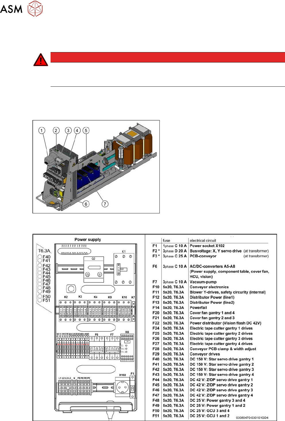
3.4.1 Overview
The power supply unit is mounted on a compact rack unit and is located between location 3 and 4.
A lockable door prevents access to the power supply.
Fig.48: Power supply (US version)
Power supply [00354626-xx]
1. Motor protection switch with motor pro-
tection trip block
2. LEDs, microfuses (SP distributor assembly
board (A10), under the mesh cover)
3. Output coupling link
4. Two boards are fitted above one another
here.
Inrush current limiter board for servo
Inrush current limiter board for transformer
5. Line filter, load add circuit, ballast resistor
(under the mesh cover)
6. Protective contactor combination
7. AC/DC converter A5 to A8
Fig.49: Overview fuses