00197042-04_SM_X-Serie-S_Customer_EN.pdf - 第58页
3 Power supply 3.4 Power supply and transformer module (up to serial number Gxxx) 58 Service Manual SIPLACE X-Serie S 06/2019 3.4.6 Replacing the inrush current limitation for the servo (A3) Parts, equipment and tools ● …
3 Power supply
3.4 Power supply and transformer module (up to serial number Gxxx)
Service Manual SIPLACE X-Serie S 06/2019 57
3.4.5 Replacing the inrush current limiter for the transformer (A2)
Parts, equipment and tools
●
Inrush current limiter board transformer [03066830-xx]
Overview
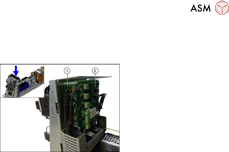
Fig.55: Overview of inrush current limiter board
1. Inrush current limiter board - servo unit
(with three connectors) (A3)
2. Inrush current limiter board - trans-
former (with six connectors) (A2)
Removal
► Switch off the machine, disconnect it from the power supply and secure it to prevent
unauthorized reactivation.
1.2 "Preparatory work..." [}16]
► Before you start working, check the power supply for absence of voltage and observe the
waiting times!
► Remove the mesh cover on the boards. To do this, remove the four screws on the side of the
cover.
► Unplug all electrical connections to the inrush current limiter transformer. Mark their positions,
to make clear assignment easier later on.
► Remove the screws fastening the inrush current limiter for the transformer and then remove
this.
Installation
► Follow the removal instructions in reverse order for installation. Also observe the following
instructions:
– Make sure that the input voltage has been set correctly at the inrush current limiter trans-
former (see label on the mesh cover).
See also
2 3.4.4 "Checking the Input Voltage at the Inrush Current Limitation Board" [}56]
3 Power supply
3.4 Power supply and transformer module (up to serial number Gxxx)
58 Service Manual SIPLACE X-Serie S 06/2019
3.4.6 Replacing the inrush current limitation for the servo (A3)
Parts, equipment and tools
●
Inrush current limiter board servo [03058951-xx]
Overview
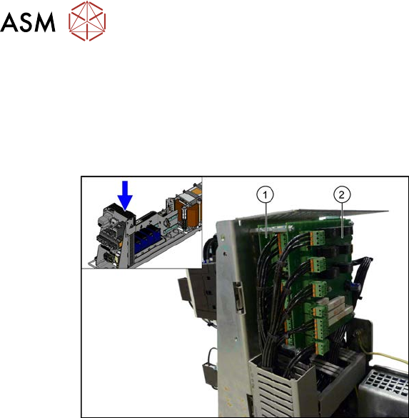
Fig.56: Inrush current limiter board
1. Inrush current limiter board - servo unit
(with three connectors) (A3)
2. Inrush current limiter board - trans-
former (with six connectors) (A2)
Removal
► Switch off the machine, disconnect it from the power supply and secure it to prevent
unauthorized reactivation.
1.2 "Preparatory work..." [}16]
► Before you start working, check the power supply for absence of voltage and observe the
waiting times!
► Remove the mesh cover on the boards. To do this, remove the four screws on the side of the
cover.
► Unplug all electrical connections to the inrush current limiter transformer. Mark their positions,
to make clear assignment easier later on.
► Remove the screws fastening the inrush current limiter transformer and then remove this in-
rush current limiter.
► Unplug all electrical connections to the inrush current limiter for the servo. Mark their posi-
tions, to make clear assignment easier later on.
► Remove the screws fastening the inrush current limiter for the servo and then remove this
servo.
Installation
► Follow the removal instructions in reverse order for installation. Also observe the following
instructions:
– Make sure that the input voltage has been set correctly at the inrush current limiter trans-
former (see label on the mesh cover).
See also
2 3.4.4 "Checking the Input Voltage at the Inrush Current Limitation Board" [}56]
3 Power supply
3.4 Power supply and transformer module (up to serial number Gxxx)
Service Manual SIPLACE X-Serie S 06/2019 59
3.4.7 Inrush current limiter servo (A1)
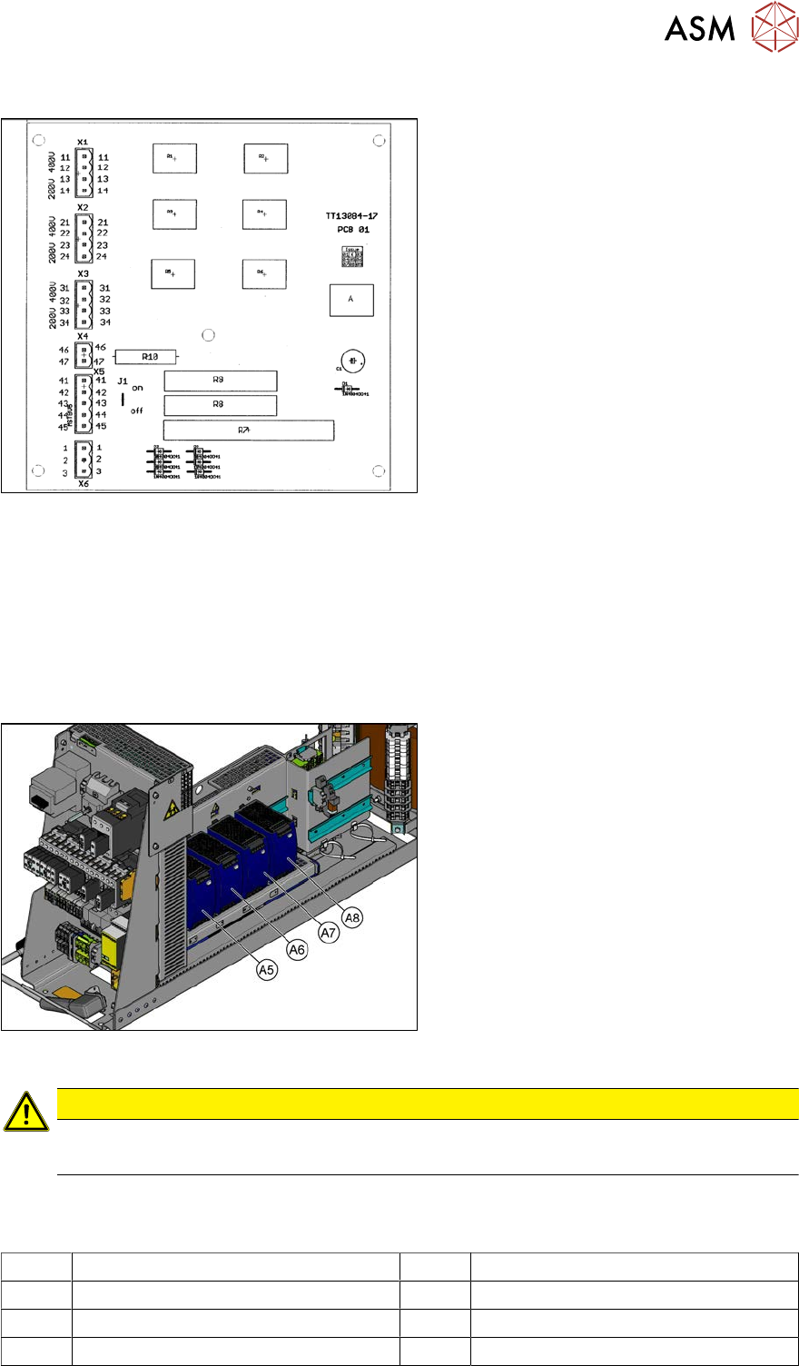
Fig.57: 03066830-01
Jumper J1:
SIPLACE HF/X-Series: jumper to ON
SIPLACE SX4/X-Series S: jumper to OFF
SIPLACE SX1/SX2: The jumper is not quer-
ied here. The jumper setting is therefore ir-
relevant.
3.4.8 Replacing the AC/DC Converter (A5 to A8)
Parts, equipment and tools
●
AC/DC converter (A5, A6, A7) [03055232-xx]
●
AC/DC converter (A8) [03076588-xx]
Overview
Fig.58: AC/DC converter
The AC/DC converters are located in the
rack unit between location 3 and 4.
A5) AC/DC converter (24 VDC, set to 25
VDC)
for Power Fail, safety circuit SSK, tape cut-
ter, PCB handling
The power fail signal is generated by the
AC/DC converter A5 and sent to the GCU
and HCU. (X200:9, X200:10)
A6) AC/DC converter (27 VDC)
for FCU (gantry 1 and 4)
A7) AC/DC converter (27 VDC)
for FCU (gantry 2 and 3)
A8) AC/DC converter (36 VDC, set to 42
VDC)
for HCU (gantry 1 to 4)
CAUTION
Check the values
► Check the set values and correct if necessary.
To A5:
There is 24V present at the following fuses:
F10 Conveyor electrics F11 Y motor fan, safety circuit (internal)
F12 Distributor power (line 1) F13 Distributor power (line 2)
F14 Power fail F20 Cover fan gantry 1 and 4
F21 Cover fan gantry 2 and 3