00197042-04_SM_X-Serie-S_Customer_EN.pdf - 第67页
3 Power supply 3.4 Power supply and transformer module (up to serial number Gxxx) Service Manual SIPLACE X-Serie S 06/2019 67 3.4.14 Replacing the socket Parts, equipment and tools Fig.67: Socket 1. Socket, rail-mounted…
3 Power supply
3.4 Power supply and transformer module (up to serial number Gxxx)
66 Service Manual SIPLACE X-Serie S 06/2019
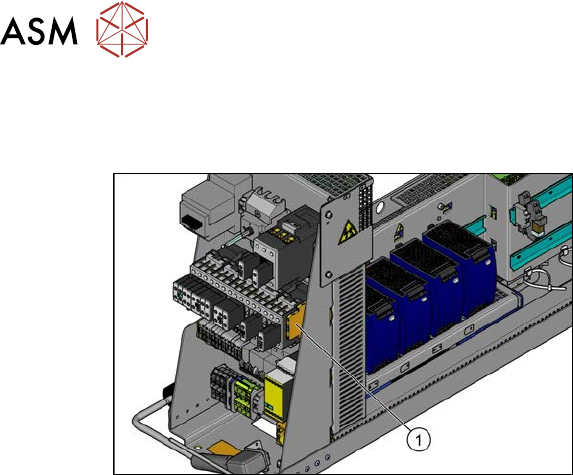
3.4.13 Replacing the output coupling link (K7)
Parts, equipment and tools
Fig.66: Output coupling link
1. Output coupling link 24V AC/DC 1W
[03065954-xx]
Removal
► Switch off the machine, disconnect it from the power supply and secure it to prevent
unauthorized reactivation.
1.2 "Preparatory work..." [}16]
► Before you start working, check the power supply for absence of voltage and observe the
waiting times!
► Unplug all connections to the output coupling link. You might like to mark their positions to
make clear assignment easier later on.
► Take the output coupling link off the rail.
Installation
► Follow the removal instructions in reverse order for installation.
3 Power supply
3.4 Power supply and transformer module (up to serial number Gxxx)
Service Manual SIPLACE X-Serie S 06/2019 67
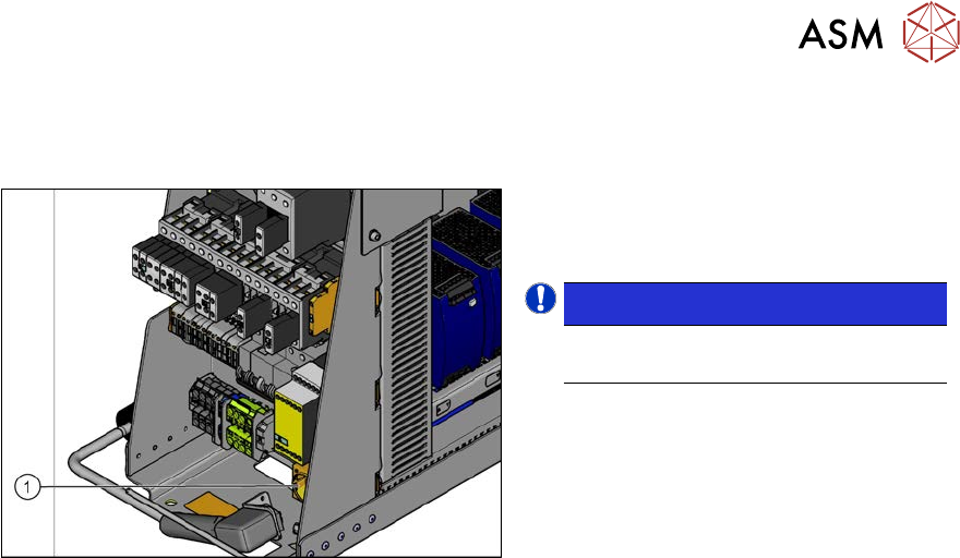
3.4.14 Replacing the socket
Parts, equipment and tools
Fig.67: Socket
1. Socket, rail-mounted SD-D/SC/LA/GY
[00375320‑xx]
NOTICE!
The socket might be not be fitted in
some machine versions.
.
Removal
► Switch off the machine, disconnect it from the power supply and secure it to prevent
unauthorized reactivation.
1.2 "Preparatory work..." [}16]
► Before you start working, check the power supply for absence of voltage and observe the
waiting times!
► Unplug all connections to the socket. You might like to mark their positions to make clear as-
signment easier later on.
► Take the socket off the rail.
Installation
► Follow the removal instructions in reverse order for installation.
3 Power supply
3.4 Power supply and transformer module (up to serial number Gxxx)
68 Service Manual SIPLACE X-Serie S 06/2019
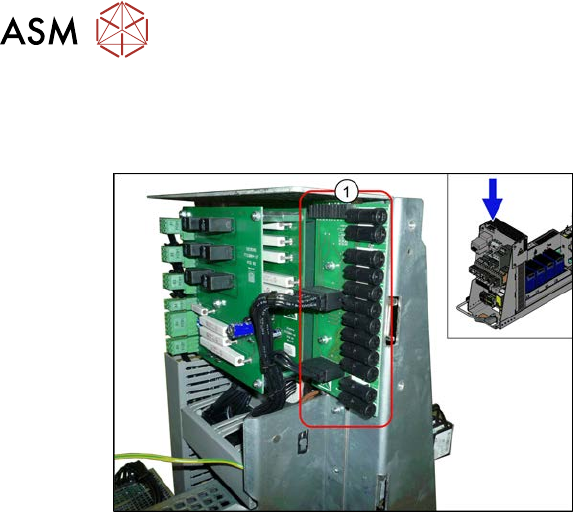
3.4.15 Replacing the SP splitter (A10)
Parts, equipment and tools
Fig.68: SP splitter (A10)
1. SP splitter (A10) [03076607‑xx]
●
12x microfuse 5x20/T6.3A/ceramic
[03010626-xx] (supplied – see machine
service box)
Removal
► Switch off the machine, disconnect it from the power supply and secure it to prevent
unauthorized reactivation.
1.2 "Preparatory work..." [}16]
► Before you start working, check the power supply for absence of voltage and observe the
waiting times!
► Loosen the screws fastening the mesh cover on the SP splitter and then remove the mesh
cover.
► Unplug all electrical connections to the SP splitter. Mark their positions, to make clear assign-
ment easier later on.
► Loosen the screws fastening the SP splitter and then remove this.
Installation
► Follow the removal instructions in reverse order for installation.