00197042-04_SM_X-Serie-S_Customer_EN.pdf - 第71页
3 Power supply 3.4 Power supply and transformer module (up to serial number Gxxx) Service Manual SIPLACE X-Serie S 06/2019 71 Removal ► Switch off the machine, disconnect it from the power supply and secure it to prevent…
3 Power supply
3.4 Power supply and transformer module (up to serial number Gxxx)
70 Service Manual SIPLACE X-Serie S 06/2019
3.4.16 Replacing the microfuse (F40 to F51)
Parts, equipment and tools
●
Microfuse 6.3A T / 150VDC [03010626-xx]
NOTICE
Fuses
A fuse kit for the power supply is included with the delivery of the machine in a separate
package or may be in the power supply.
Overview
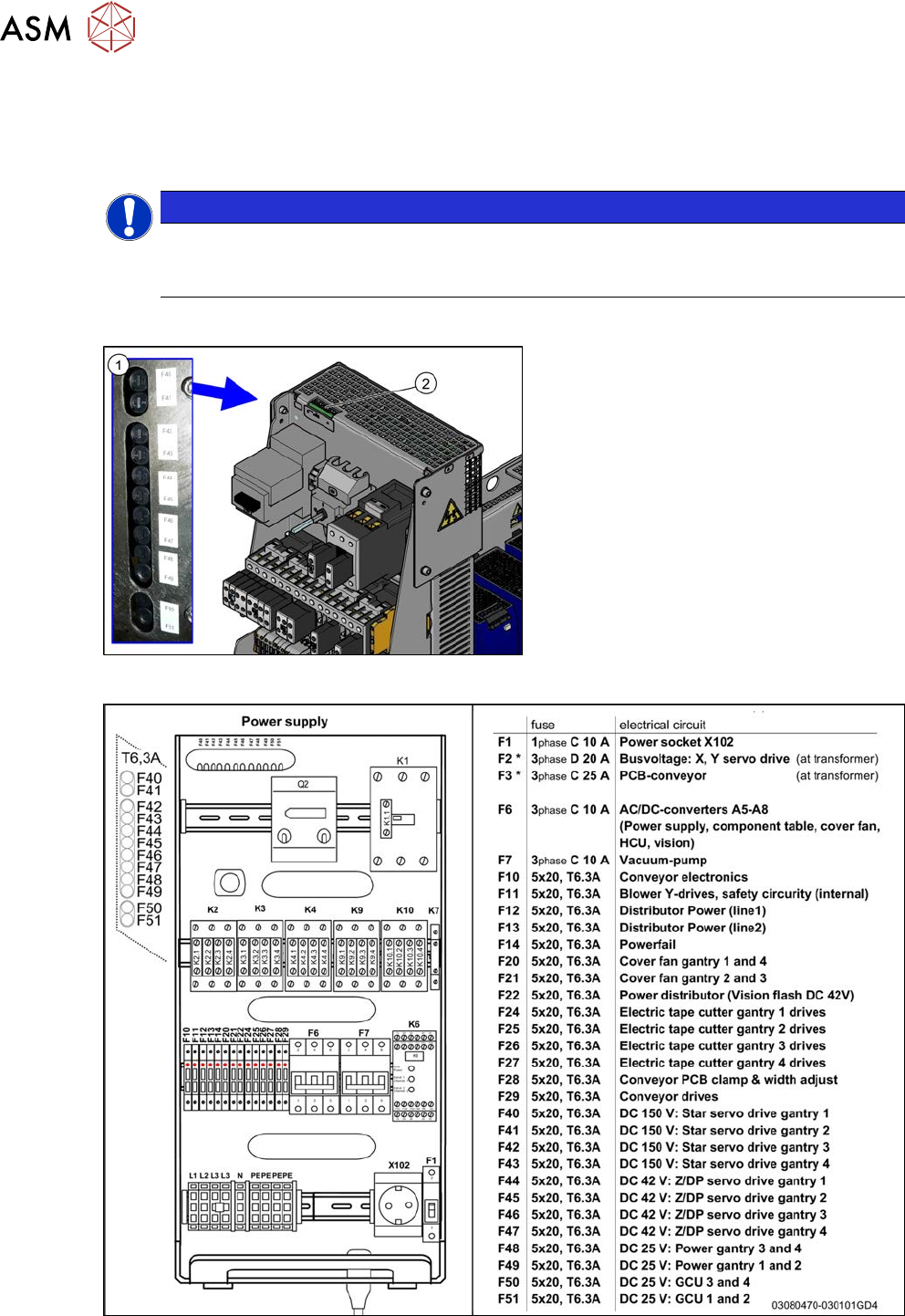
Fig.70: Microfuses and LEDs
1. Microfuses F40 to F51
2. LED D40 to D51
The LEDs show the operational readiness of
the individual microfuses.
Fig.71: Microfuses
3 Power supply
3.4 Power supply and transformer module (up to serial number Gxxx)
Service Manual SIPLACE X-Serie S 06/2019 71
Removal
► Switch off the machine, disconnect it from the power supply and secure it to prevent
unauthorized reactivation. Observe the instructions in section 1.2 "Preparatory work..." [}16].
► Before you start working, check the power supply for absence of voltage and observe the
waiting times!
► Use a suitable screwdriver to turn the fuse holder out of its socket.
► Remove the old microfuse from the fuse holder and replace this with a new microfuse of the
same type.
Installation
► Follow the removal instructions in reverse order for installation.
3.4.17 Replacing the main switch 3LD2
NOTICE
Missing axis support
The machine is switched on with the help of an extension axis via the protective motor
switch. When inserting the door coupling handle onto the extension axis of the protective
motor switch, the axis could move into a slanted position. In this case, high traverse forces
will be exerted against the axis coupling of the protective motor switch, which could then
break. This would then make it impossible to switch the machine on or off.
Some machines do not have this additional axis support on the protective motor switch.
This support is used to limit the slant of the extension axis and therefore to reduce the tra-
verse forces against the axis coupling.
► This axis support can be retrofitted. For details, read the Technical Information "Retro-
fit Guide Axis Support Motor Circuit Breaker PKE32/XTU-32 Assembly 3p. (Main
Switch)" [DE: TI2013-07D10] [EN: TI2013-07E10].
Parts, equipment and tools
●
Main switch 3LD2 [03059733Sxx] (US version)
NOTICE
Conversion kit USA
This main switch is only fitted in conjunction with the "USA (110V) Conversion Kit" option.
As a default, the machine is switched on via the motor protection switch "PKE32/XTU-32
assembly 3p." [03098183‑xx]. The motor protection switch is located in place of the main
switch in this case.
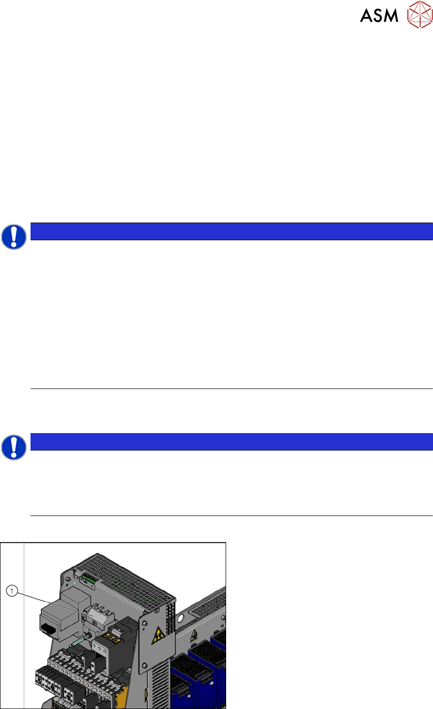
Overview
Fig.72: Main switch (using example of US version)
1. Main switch
3 Power supply
3.4 Power supply and transformer module (up to serial number Gxxx)
72 Service Manual SIPLACE X-Serie S 06/2019
Removal
► Switch off the machine, disconnect it from the power supply and secure it to prevent
unauthorized reactivation.
1.2 "Preparatory work..." [}16]
► Before you start working, check the power supply for absence of voltage and observe the
waiting times!
► Unplug all connections to the main switch. You might like to mark their positions to make clear
assignment easier later on.
► Dismantle the shafton the main switchby pressing this together at the sides and pulling it off.
You will need to use this again on the new switch. This is reused on the new switch.
► Open the lock on the rail and remove the main switch. You may need to read the manufac-
turer's instructions provided.
Installation
► Follow the removal instructions in reverse order for installation. Also observe the following
instructions:
●
Fit the shaft from the old switch onto the new switch.
3.4.18 Replacing the Motor Circuit Breaker with Motor Protection Tripping Unit
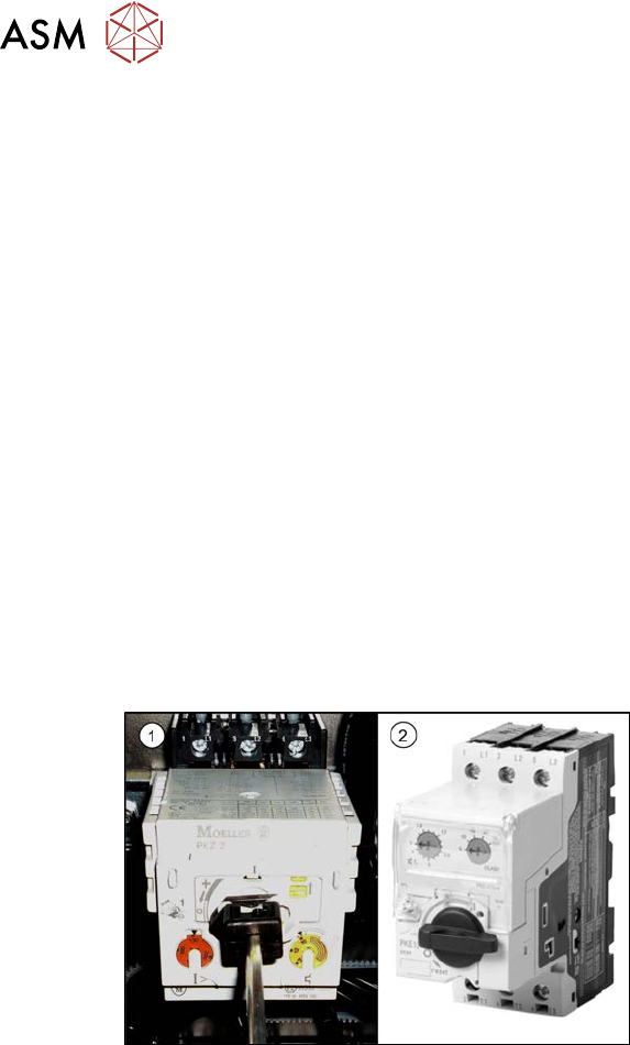
Overview
Fig.73: Motor circuit breaker – old and new version
1. Motor protection switch - old version
with motor protection trip block (discon-
tinued)
2. Motor protection switch – new version
without motor protection trip block
► Select the required chapter:
●
3.4.19 "Replacing the motor protection switch PKZ2" [}73]
●
3.4.20 "Replacing the Motor Protection Release Block (PKZ2)" [}75]
●
3.4.21 "Replacing the motor protection switch PKE32/XTU-32" [}78]