00197042-04_SM_X-Serie-S_Customer_EN.pdf - 第94页
3 Power supply 3.5 Power supply and transformer module (from serial number Hxxxx) 94 Service Manual SIPLACE X-Serie S 06/2019 Fig.109: Cover – fastening screws ► Remove the six screws (2) fastening the cover (1) . Fig…
3 Power supply
3.5 Power supply and transformer module (from serial number Hxxxx)
Service Manual SIPLACE X-Serie S 06/2019 93
3.5.6 Replacing the Contactor Safety Breaker [03112066-xx]
DANGER
High voltages
High DC voltages can be present in the contactor safety breaker.
► No parts of the contactor safety breaker may be replaced.
► Only the front cover of the contactor safety breaker may be dismantled for connecting
cables or removing the complete unit.
► The contactor safety breaker may only be replaced as a complete unit.
Parts, equipment and tools
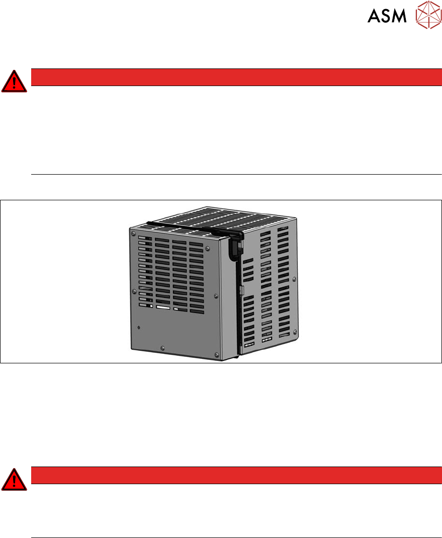
Fig.108: Contactor safety breaker [03112066‑xx]
●
Contactor safety breaker [03112066‑xx]
Removal
► Switch off the machine, disconnect it from the power supply and secure it to prevent
unauthorized reactivation.
1.2 "Preparatory work..." [}16]
DANGER
Checking for absence of voltage!
► Before you start working check the power supply for absence of voltage and observe
the waiting times! For more information about this read section 3.5.4 "Checking For
Absence of Voltage" [}86].
► Pull the power supply out of the machine.
3.3 "Pulling out the Power Supply" [}51]
3 Power supply
3.5 Power supply and transformer module (from serial number Hxxxx)
94 Service Manual SIPLACE X-Serie S 06/2019
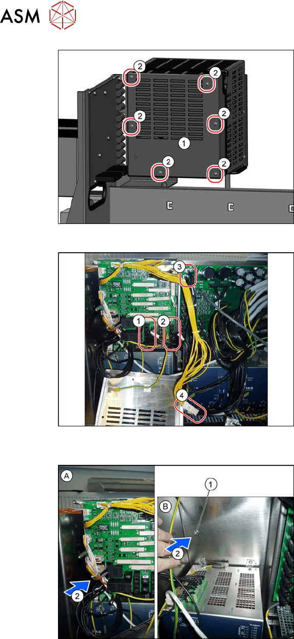
Fig.109: Cover – fastening screws
► Remove the six screws(2) fastening
the cover(1).
Fig.110: Unplugging the electrical connections (example of
SIPLACE SX1/SX2 shown)
► Unplug the electrical connections (1) to
(4). You might like to mark their posi-
tions to make clear assignment easier
later on.
Fig.111: Removing the contactor safety breaker (example of
SIPLACE SX1/SX2 shown)
Figure (B) shows the power supply; the con-
tactor safety breaker is removed for a better
view.
► Loosen the screw(1) on the rear of the
contactor safety breaker.
To access the screw, route an exten-
sion past the side of the contactor
safety breaker.
► Lift the contactor safety breaker up a
bit.
► Unplug the electrical connections
between the contactor safety breaker
and the buffer module (2).
► Lift the contactor safety breaker off.
Installation
► Follow the removal instructions in reverse order for installation. Also observe the following
instructions:
– Make sure that the cables are run correctly.
– The cables must not be pinched or rub against unprotected edges.
– Make sure that the cables are run out of the contactor safety breaker through the two re-
cessesprovided only.
3 Power supply
3.5 Power supply and transformer module (from serial number Hxxxx)
Service Manual SIPLACE X-Serie S 06/2019 95
3.5.7 Replacing the AC/DC Converter
Parts, equipment and tools
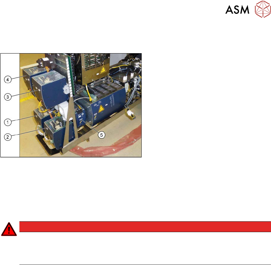
Fig.112: Overview of the AC/DC converter
1.
PS1: AC-/DC converter DC300/150V
1.3kW 3 phase [03103087‑xx]
300/160 V for gantry 1/4
2.
PS2: AC-/DC converter DC300/150V
1.3kW 3 phase [03103087‑xx]
300/160 V for gantry 2/3
3.
PS3: AC/DC converter 36V 26.7A
960W 3 phase [03103331‑xx]
→ 42 V for Vision, head, conveyor mo-
tors
4.
PS4: AC/DC converter DC24V/40A 3
phase [03102840‑xx]
→ 27 V for FCU
5. AC/DC converter DC24V/20A 3
phase [03055232‑xx]
→ 24V
Removal
► Switch off the machine, disconnect it from the power supply and secure it to prevent
unauthorized reactivation.
1.2 "Preparatory work..." [}16]
DANGER
Checking for absence of voltage!
► Before you start working check the power supply for absence of voltage and observe
the waiting times! For more information about this read section 3.5.4 "Checking For
Absence of Voltage" [}86].
► When replacing the AC/DC converter fitted at the side:
Pull the power supply out of the machine a little.
► Unplug all electrical connections from the AC/DC converter. You may want to mark the posi-
tions of these connections to make clear assignment easier later on.
► Open the lock under the AC/DC converter. Tilt the AC/DC converter slightly upwards and then
take it up and off.
Installation
► Follow the removal instructions in reverse order for installation. Also observe the following
instructions:
– Set the AC/DC converter (see 3.5.8 "Setting the Voltage on the AC/DC Convert-
ers" [}96]).