00198368-01_UM_SIPLACESX12-DockingStation_DE_EN_ZH - 第71页
User manual Docking station for SIPLACE SX component trolleys 4 Operation Edition 02/2018 4.2 Adjusting the conveyor height 71 4.2 Adjusting the conveyor height Y ou need fork wrenche s size SW 22 and SW 24 plus a spirit…
4 Operation User manual Docking station for SIPLACE SX component trolleys
4.1 Controls and displays Edition 02/2018
70
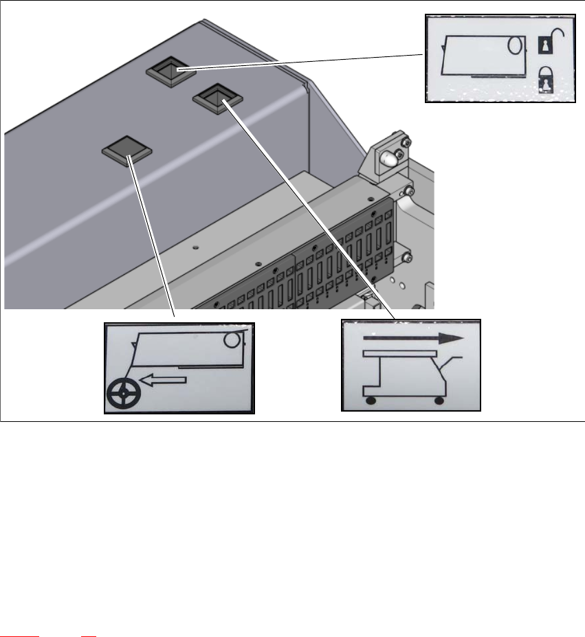
4.1.2 Controls
4
Fig. 4.1 - 2 Docking station - controls and displays
(1) Feeder module tear down (black button)
(2) Component trolley unlocking function (white button)
(3) Locking and unlocking of feeder modules (green button)
4.1.3 CAN bus addresses
The adjustable CAN bus addresses are on the label, above the switches S1 and S2 (item 6 in fig.
4.1 - 1
, page 69).
1
2
3
User manual Docking station for SIPLACE SX component trolleys 4 Operation
Edition 02/2018 4.2 Adjusting the conveyor height
71
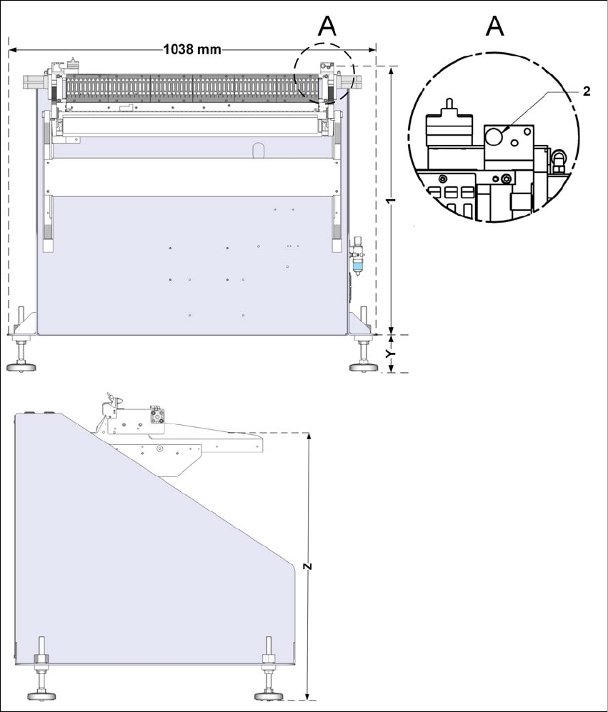
4.2 Adjusting the conveyor height
You need fork wrenches size SW22 and SW24 plus a spirit level.
4
Fig. 4.2 - 1 Adjusting the conveyor height
(1) X (floor to centering pin)
(2) Centering pin
4 Operation User manual Docking station for SIPLACE SX component trolleys
4.2 Adjusting the conveyor height Edition 02/2018
72
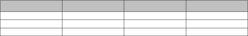
To set the conveyor height, proceed as follows:
Loosen the locknuts on all base feet.
Use the adjusting screws to set the size Y (see table).
Check whether the machine is horizontally level.
4
Machine height Size X Size Y Size Z
900mm 859mm 100mm 770mm
930mm 889mm 130mm 800mm
950 mm 909mm 150mm 820mm