YRM20_Mainte_E.pdf - 第122页
5. 1-year maintenance 3-55 Chapter 3 Periodic maintenance items 4 Detach t he filt er eleme nt. Oil mist filter element: The mist filter element is attache d to the scr ew protruded fr om the filter housing. Detach t he m…
5. 1-year maintenance
3-54
Chapter 3 Periodic maintenance items
5.5 Base section
5.5.1 Replacing the air and mist filter element and cleaning the cup
An air filter and an oil mist filter are installed in YRM20 to prevent oil, water, and impurities in the air
compressor from entering the machine.
This section describes the procedure for inspecting and cleaning these filters and also for replacing the filter
media (filter elements). Detach the air coupler from the air supply fitting to ensure worker safety.
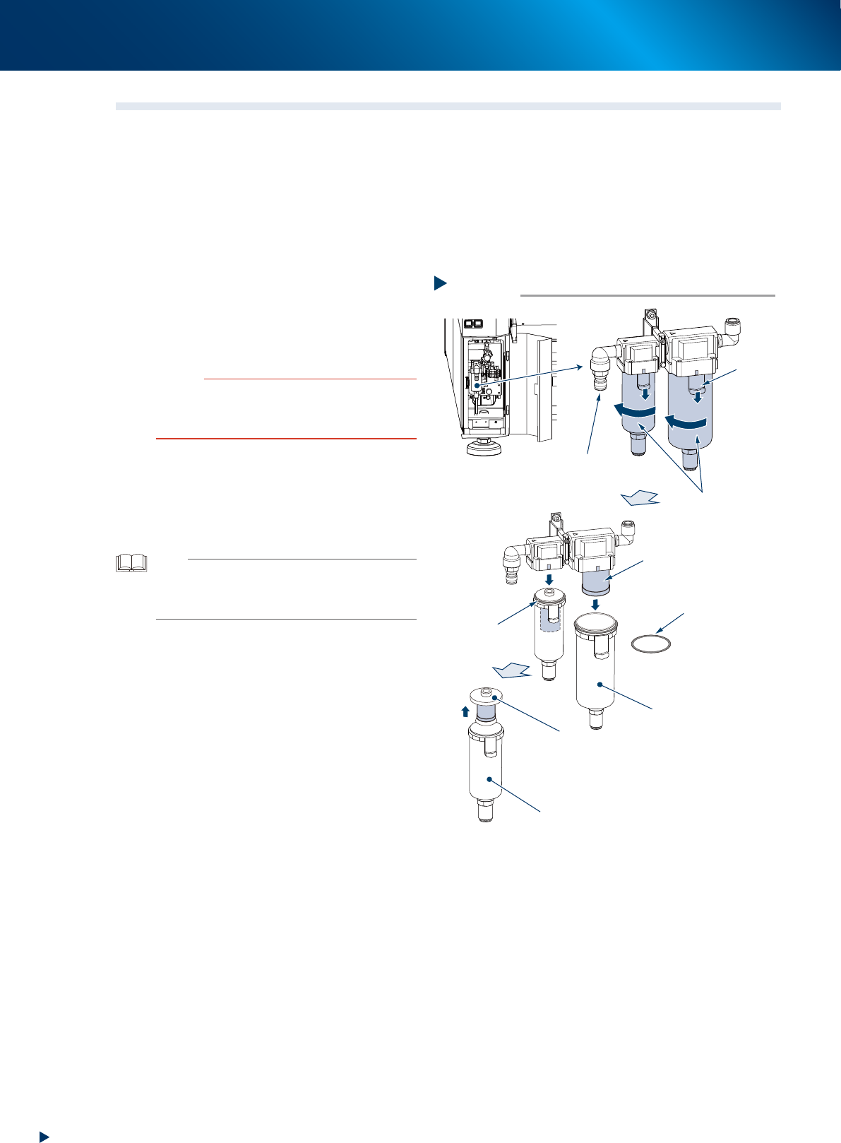
1
Detach the air coupler of air supply.
1. Rotate the "Air supply/exhaust" switch to
left (EXH) to shut down the air supply.
2. Detach the air coupler from the air supply
fitting.
c
CAUTION
When disconnecting the air coupler from the air supply
fitting, be aware that a loud air exhaust sound occurs.
Also be aware of oil, water, and impurities that may spray
out.
2
Check the inside of the filer cup visually
for oil or water deposits in the filter
cup.
If the window is dirty, follow the procedure of
Step 3 to Step 6 to clean the filter cup.
TIP
The drain cock at the bottom of the filter cup is an
auto-drain type. It automatically drains the oil or water
when deposited in the cup. We recommend connecting a
hose to this drain cock.
3
Detach the filter cup.
Oil mist filter:
Push down the cup's button, and turn the cup
45-degree counterclockwise. Then pull
downward to detach it.
Air filter:
1. Push down the cup's button, and turn the
cup 45-degree clockwise. Then pull
downward to detach it.
2. Pull out the internal filter upward.
Step 3
Detaching the air coupler
Internal filter
Detaching the filter cup
Filter cup
Air filter
Oil mist filter
Button
O-ring for cup
O-ring for cup
Oil mist filter element
53383-KMX-10
5. 1-year maintenance
3-55
Chapter 3 Periodic maintenance items
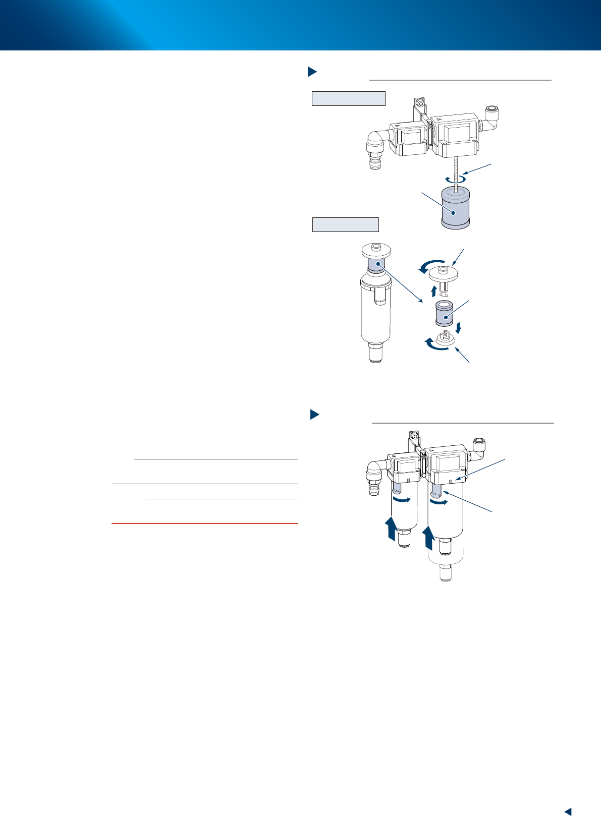
4
Detach the filter element.
Oil mist filter element:
The mist filter element is attached to the screw
protruded from the filter housing. Detach the
mist filter element by rotating.
Air filter element:
The filter element is set in the cup between the
upper and lower adapters. Pull out upward with
adapters and detach the filter element by
rotating the adapters.
5
Check the filter element for soiling and
clogging. If soiled, replace it with new
one prescribed in the Consumable Parts
List.
6
Clean the inside of filter cup.
1. Lightly clean the filter cup with water.
2. Pour water-diluted neutral detergent into the
filter cup and clean the inside while shaking
it.
3. Air blow the filter cup and wipe away any
moisture with clean cloth or paper.
7
Attach the filter element and cup.
1. Attach the filter element by the reverse
procedure of detaching.
2. Set the cup's button to the pulling out
position (45-degree to left) and push the cup
upward.
3. Turn the filter cup to right until it aligns with
the marking of the filter housing.
n
NOTE
The filter cup clicks when it is rotated to the marked
position.
c
CAUTION
Make sure not to drop off the O-ring for cup upon
attaching.
8
Reconnect the air coupler.
1. Reconnect the air coupler and check that no
air is leaking.
2. Turn the "Air supply/exhaust" switch to right
(SUP) to resume the air supply.
Mist filter element
Detaching filter element
Step 4
Filter element
Attached by screw
Adopter
Adopter
Oil mist filter
Air filter
53384-KMX-00
Attaching the cup
Step 7
Marking
Button
53385-KMX-00
5. 1-year maintenance
3-56
Chapter 3 Periodic maintenance items
5.5.2 Replacing the filter element of vacuum pump
One air filter is used per one vacuum pump installed in machine.
Inspect the filter at least once a month and the replacement of the inner media (filter element) is
recommended once a year to prevent the trouble caused by clogging.
Make sure to detach the air coupler from the air supply fitting to ensure worker safety.
█
Precautions when handling the vacuum pump
• The inside of the pump is hot shortly after operation. Wait about 10 minutes after stopping operation
and make sure the pump has cooled down before starting the replacement.
• Wear dust-proof mask and gloves upon replacing consumable parts. Otherwise you might inhale
small particles of worn parts or the hand might be injured.
• The pump weighs approximately 10 kg. Do not drop the pump to avoid injury to your feet and handle
the pump carefully not to hurt your back.
1
Prepare for work.
1. Press the emergency stop button and detach
the feeder exchange carriage on machine
front side.
2. Close applications and turn OFF the machine
power.
2
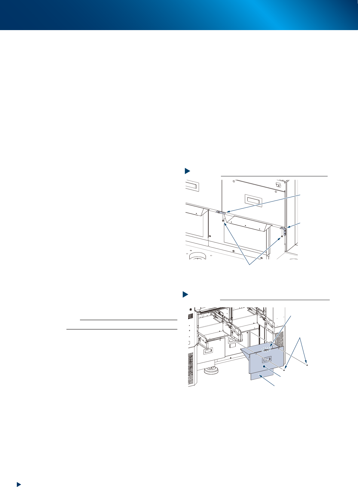
Remove the mounting screws located
beneath the safety cover of tape cutter
(hereinafter referred to as cutter cover)
using Phillips screwdriver.
The mounting screws are at left and
right of connecting point, and the point
connected to machine body.
3
Remove the cutter cover.
1. Remove the mounting screw of the cutter
cover (right front of machine rear) using
Phillips screwdriver.
2. Pull out the cutter cover frontward.
n
NOTE
The cutter cover is installed an interlock key.
Removing the mounting screw
Step 2
Mounting screw
Left-right
connecting
point
Connecting
point to
machine body
53386-KMX-00
Step 3
Detaching the cutter cover (machine rear)
Cutter cover
Mounting screw
Interlock key
Preventing cut debris splattering sheet
5339E-KMX-00