YRM20_Mainte_E.pdf - 第130页
6. 2-year maintenance 3-63 Chapter 3 Periodic maintenance items ► Switching vacuum/blow with spool The RM head switches vacuum/blow by moving up/down the spool, using up/down operation of V -axes located at left and righ…
6. 2-year maintenance
3-62
Chapter 3 Periodic maintenance items
6.2.3 Cleaning/lubricating the vacuum selector (spool)
The RM head switches between vacuum and blow by way of an up and down spool movement in each head.
The spool should be cleaned and lubricated about every 2 years as a general guide.
Lubricating the spool requires the dedicated grease (grease for spool: GREASE 30G KMB-M3854-00X).
1
Prepare for work.
e
1. Remove all items sensitive to magnetic fields
such as wristwatches and magnetic ID cards.
2. Press the emergency stop button and detach
the feeder exchange carriage. Then open
the machine safety cover.
3. Move the head unit to a convenient position
for maintenance work and place a square
cloth beneath it.
2
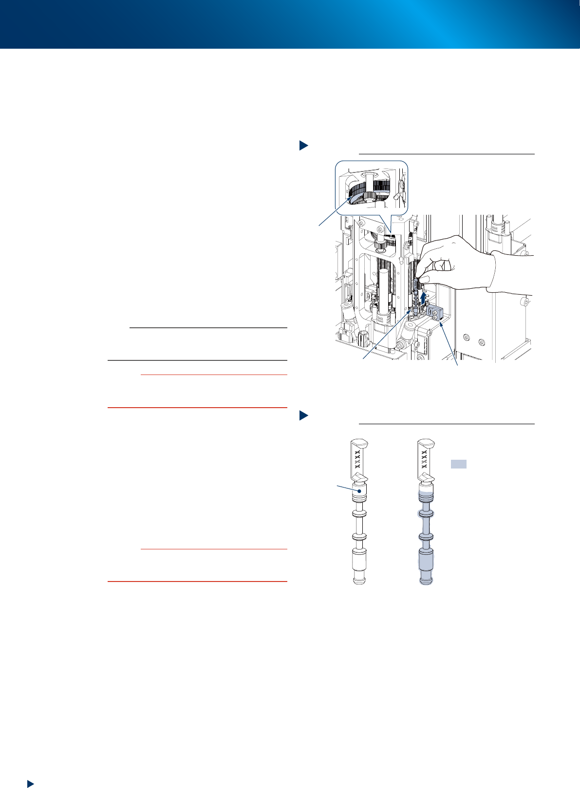
Pull out the spool by gripping its upper
side with fingers and pulling out
upward.
Use a longnose pliers or the similar if the spool
is difficult to pinch with fingers.
n
NOTE
Id the spool locates where being difficult to lower, see
"Lowering RM head/nozzle shafts" above and turn the
N-axis gear to rotate the rotary.
c
CAUTION
Remove the spool completely. Turning the rotary unit while
removing the spool may cause contact with the V-axis
(Valve axis / spool up-down axis).
3
Clean the spool by wiping off old grease
and dirt on the spool using a lint-free
cloth.
4
Apply a thin uniform coat of the
specified grease (dedicated grease for
spool) by hand to the spool.
5
Return the spool to its original position
and insert it all the way seated.
c
CAUTION
Firmly insert the spool all the way to its original position.
Turning the rotary unit while inserting the spool may cause
contact with the V-axis (Valve axis / spool up-down axis).
6
Clean and lubricate the other spools.
1. Clean/lubricate rest of spools with the same
procedures as Step 2 to 5.
2. Retrieve a square cloth after working.
Step 2
Pulling out spool
Spool
N-axis gear
V (valve) axis
53389-KMX-00
:Grease application
area
Lubricating spool
Step4
Spool
53390-KMX-00
6. 2-year maintenance
3-63
Chapter 3 Periodic maintenance items
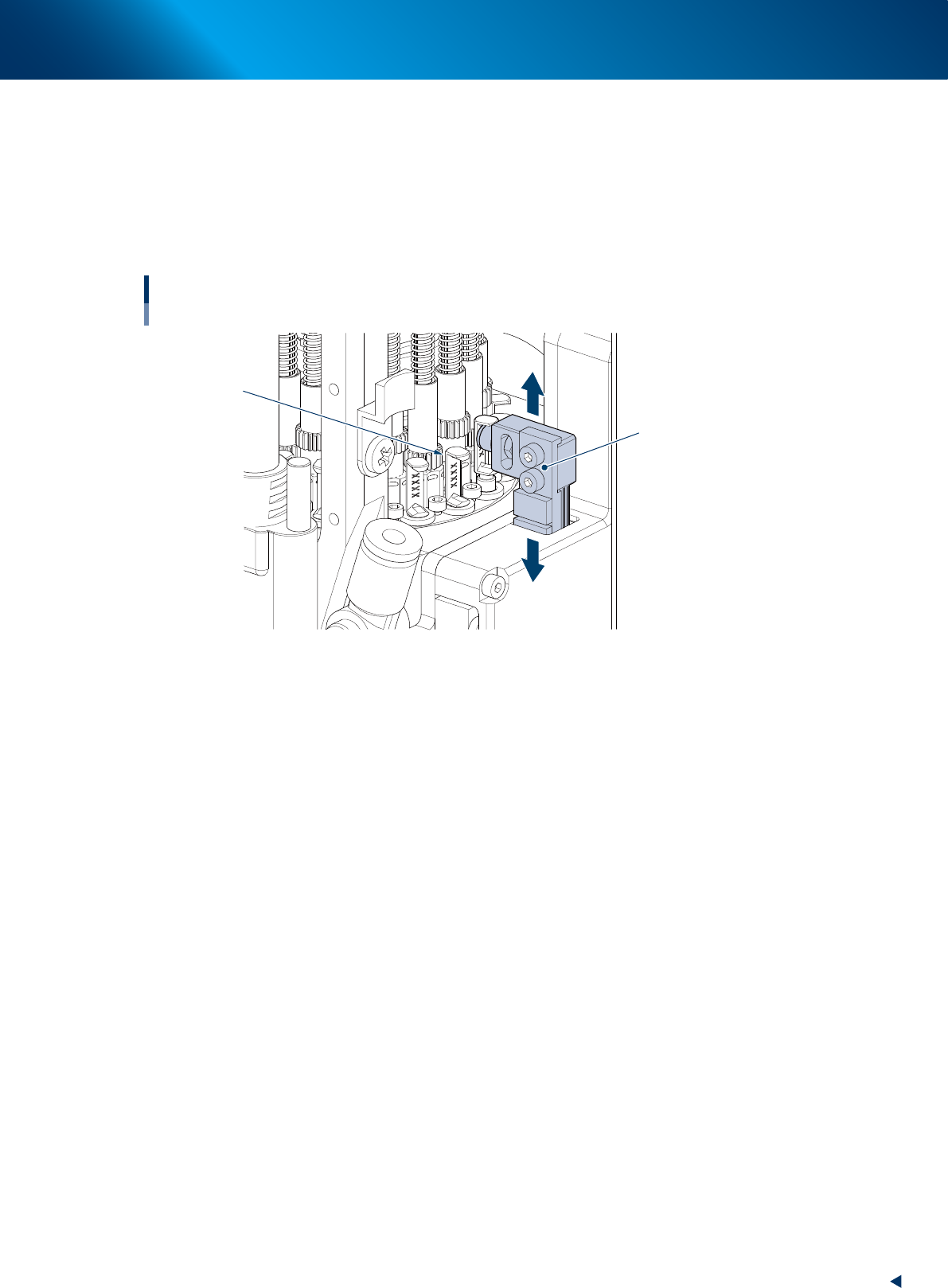
►
Switching vacuum/blow with spool
The RM head switches vacuum/blow by moving up/down the spool, using up/down operation of V-axes
located at left and right side of head unit.
• When the spool descends, air is supplied to nozzle shaft.
• When the spool ascends, nozzle shaft is vacuated.
Moving up/down spool with V-axis
Spool
Moves up/down spool
V-axis
533G6-KMX-00
6. 2-year maintenance
3-64
Chapter 3 Periodic maintenance items
6.2.4 Replacing the blow valves
The blow valve (rod 1, rod 2 and blow valve) of the air lines in RS head requires to replace every 2 years.
1
Prepare for work.
e
1. Remove all items sensitive to magnetic fields
such as wristwatches and magnetic ID cards.
2. Press the emergency stop button and detach
the feeder exchange carriage.
3. Open the machine safety cover and move the
head unit to a convenient position for
maintenance work. Then place a square cloth
beneath it.
4. Turn OFF the machine and the air supply to
the machine.
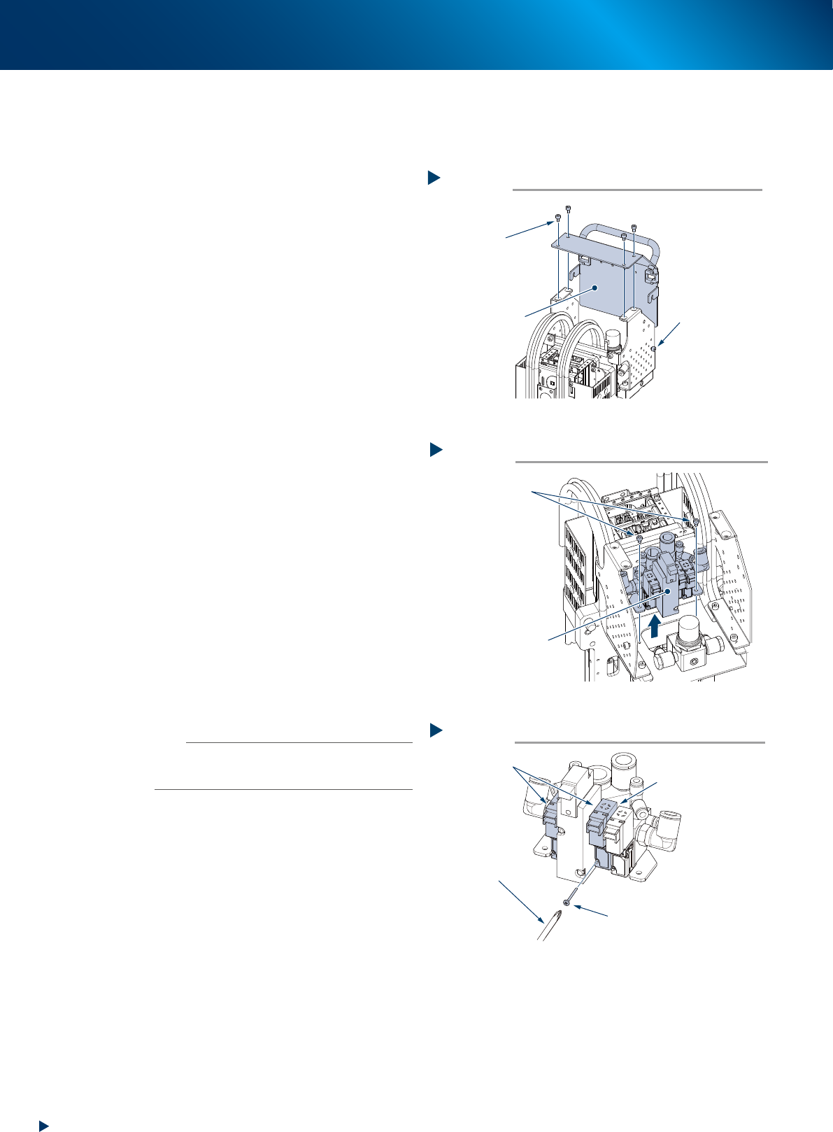
2
Detach the cover of upper part of head.
1. Loosen the bolts mounting the both sides of
the head (1 for each sides) using a hexagon
wrench (3mm).
2. Detach the 4 bolts mounting the upper surface
of cover using a hexagon wrench (3mm).
3
Remove the valve assembly.
1. Detach all the air hoses and connectors
connecting to the valve assembly.
2. Remove the 2 mounting bolts using a hexagon
wrench (3mm) and pull out the valve
assembly.
4
Replace the blow valve.
1. Detach the valve mounting screws with Phillips
precision screwdriver.
2. Replace the valve with new one.
5
Return the valve assembly to its original
position.
1. Attach the valve assembly to head.
2. Return the connectors and air hoses to their
original position..
n
NOTE
The packing is attached to the back of the valve. Replace the
valve with a new one while carefully checking the packing
for dropping or catching.
6
Return the upper cover of head to its
original position.
1. Return the head upper cover to its original
position.
2. Retrieve the square cloth and close the machine
safety cover.
Detaching the cover of upper part of head
Step 2
Upper surface
mounting bolt (4)
Cover of upper part
of head
Lateral side
mounting bolt
(1 for each sides)
Loosen, but not detach
533D7-KMX-00
Removing the valve assembly
Step 3
Detach all the connected
connector and air hoses
Mounting bolt
Valve assembly
533D8-KMX-00.ai
Replacing the blow valve
Step 4
Precision Phillips
screwdriver
[Caution for dropping]
A packing is installed
at reverse side of valve
Valve mounting screw
Blow valve
533D9-KMX-00