YRM20_Mainte_E.pdf - 第132页
6. 2-year maintenance 3-65 Chapter 3 Periodic maintenance items 7 Check the valve oper ation. 1. T urn on the air supply and main power supply . Then launch the applications 2. Select the [Unit]-[Head] t ab. 3. Press the…
6. 2-year maintenance
3-64
Chapter 3 Periodic maintenance items
6.2.4 Replacing the blow valves
The blow valve (rod 1, rod 2 and blow valve) of the air lines in RS head requires to replace every 2 years.
1
Prepare for work.
e
1. Remove all items sensitive to magnetic fields
such as wristwatches and magnetic ID cards.
2. Press the emergency stop button and detach
the feeder exchange carriage.
3. Open the machine safety cover and move the
head unit to a convenient position for
maintenance work. Then place a square cloth
beneath it.
4. Turn OFF the machine and the air supply to
the machine.
2
Detach the cover of upper part of head.
1. Loosen the bolts mounting the both sides of
the head (1 for each sides) using a hexagon
wrench (3mm).
2. Detach the 4 bolts mounting the upper surface
of cover using a hexagon wrench (3mm).
3
Remove the valve assembly.
1. Detach all the air hoses and connectors
connecting to the valve assembly.
2. Remove the 2 mounting bolts using a hexagon
wrench (3mm) and pull out the valve
assembly.
4
Replace the blow valve.
1. Detach the valve mounting screws with Phillips
precision screwdriver.
2. Replace the valve with new one.
5
Return the valve assembly to its original
position.
1. Attach the valve assembly to head.
2. Return the connectors and air hoses to their
original position..
n
NOTE
The packing is attached to the back of the valve. Replace the
valve with a new one while carefully checking the packing
for dropping or catching.
6
Return the upper cover of head to its
original position.
1. Return the head upper cover to its original
position.
2. Retrieve the square cloth and close the machine
safety cover.
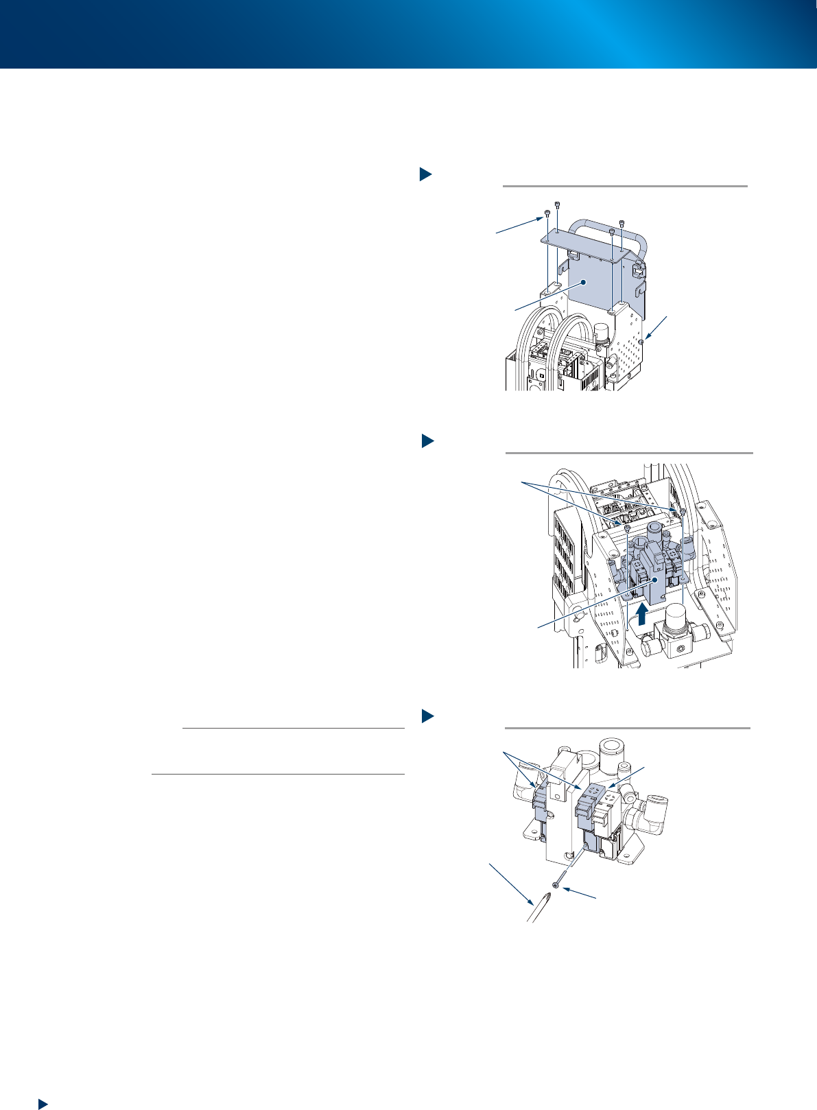
Detaching the cover of upper part of head
Step 2
Upper surface
mounting bolt (4)
Cover of upper part
of head
Lateral side
mounting bolt
(1 for each sides)
Loosen, but not detach
533D7-KMX-00
Removing the valve assembly
Step 3
Detach all the connected
connector and air hoses
Mounting bolt
Valve assembly
533D8-KMX-00.ai
Replacing the blow valve
Step 4
Precision Phillips
screwdriver
[Caution for dropping]
A packing is installed
at reverse side of valve
Valve mounting screw
Blow valve
533D9-KMX-00
6. 2-year maintenance
3-65
Chapter 3 Periodic maintenance items
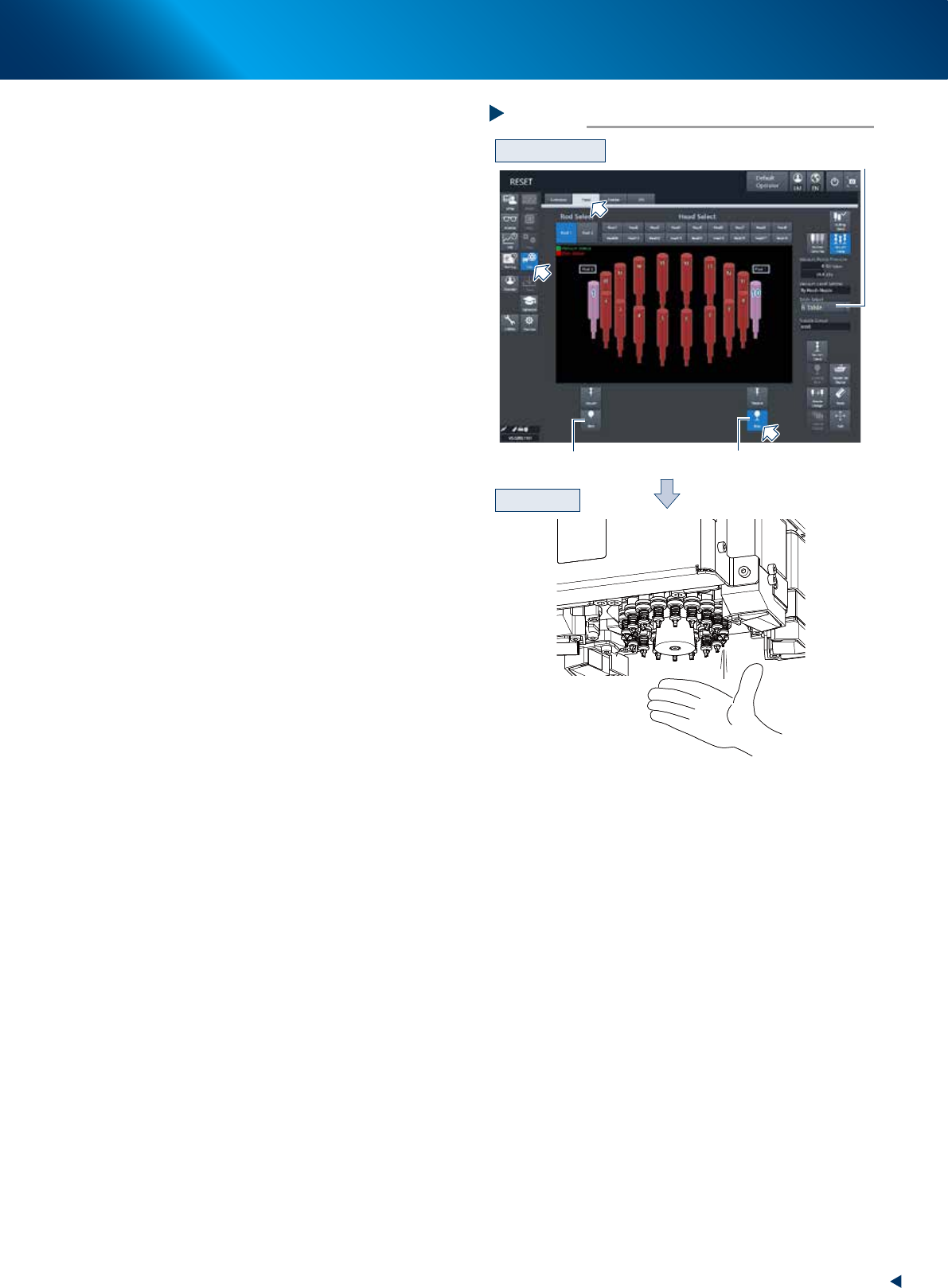
7
Check the valve operation.
1. Turn on the air supply and main power supply.
Then launch the applications
2. Select the [Unit]-[Head] tab.
3. Press the [Table select] button and select the
table (head unit) that the valve was replaced.
4. Press the [Blow] button that the rod was
replaced (Rod 1or Rod 2).
e
5. Press the emergency stop button. Open the
machine safety cover and check that the blow
air is property flowing out from the tip of the
head.
Checking RM head blow operation
Step 7
[Blow] button for rod 1
Table Select
[Blow] button for rod 2
Checking blow
B table as example
54327-KMX-00
Checking RM head blow operation
Step 7
[Blow] button for rod 1
Table Select
[Blow] button for rod 2
Checking blow
B table as example
7. 3-year maintenance
3-66
Chapter 3 Periodic maintenance items
7. 3-year maintenance
This section describes 3-year maintenance items.
7.1 Replacement of the vacuum pumps
Though it may vary with the machine operating status, the vacuum pump should normally be replaced every
3 years.
1
Prepare for work.
1. Press the emergency stop button and detach
the feeder exchange carriage on the front
side of machine.
2. Close the applications and power off the
machine.
2
Detach all the cover referring the
"5.5.2 Replacing the filter element of
vacuum pump" above.
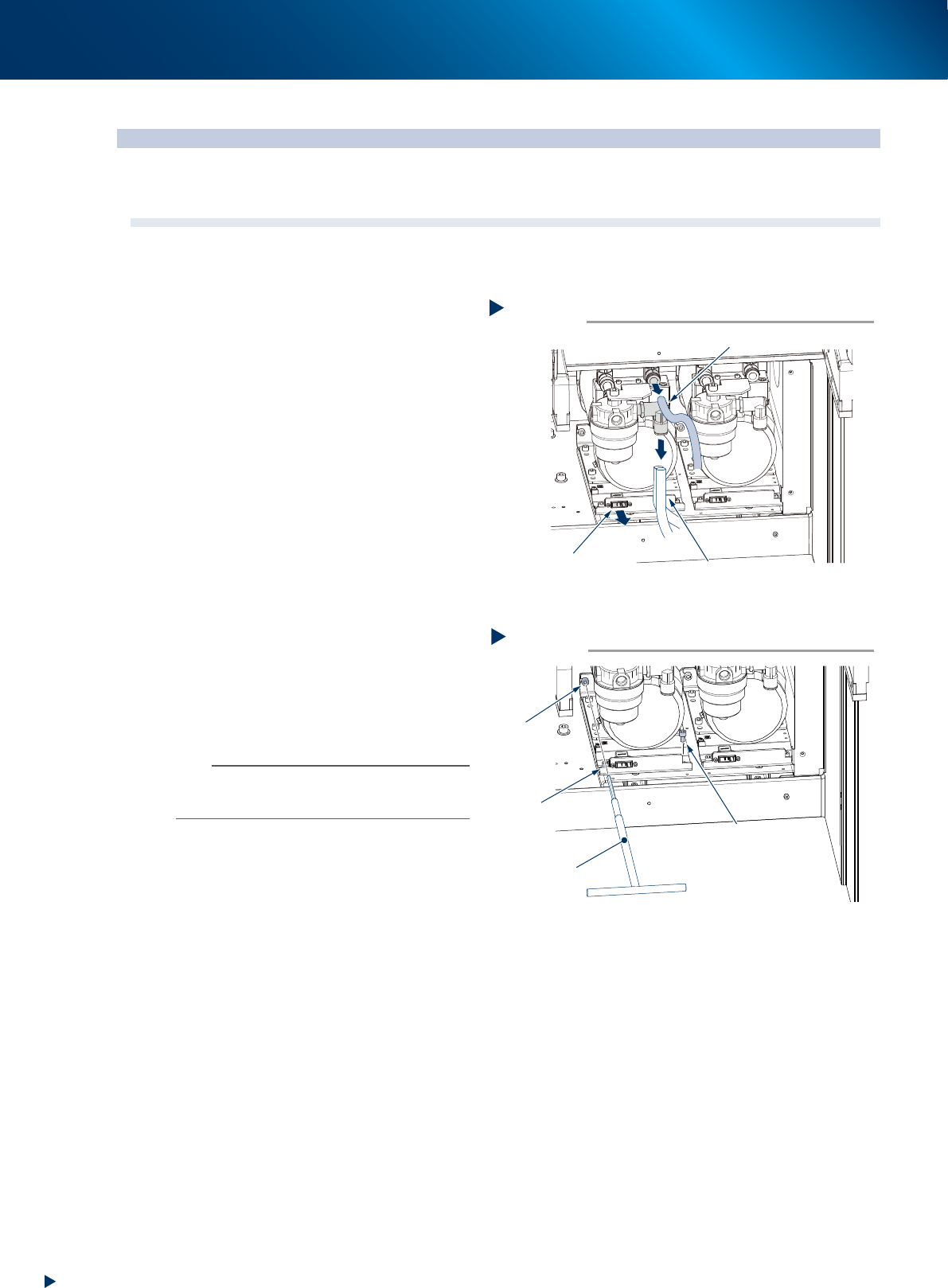
3
Detach the air hoses and connector.
1. Detach the 1 blue air hose and 2 white, 3 in
all air hoses.
2. Detach the connector illustrated at right.
4
Loosen the mounting bolts at rear side
and left front.
1. Using a T-type wrench (5mm), loosen the
mounting bolt at rear side illustrated at right
to an extent as not coming off.
2. Also, using a hexagon wrench (5mm),
loosen the mounting bolt at left front of
machine to an extent as not coming off.
n
NOTE
The mounting bolts described above are not required to
detach. The vacuum pump can be removed by only
loosening them.
5
Remove the mounting bolt at right front
using a hexagon wrench (5mm).
Removing the connector and air hoses
Step 3
1 blue air hose
2 white air hoses
Connector connection
5339G-KMX-00
Removing the mounting bolts
Step 4, 5
Rear
mounting bolt
Front left
mounting bolt
Loosen
Loosen
Remove
Front right mounting bolt
T-type wrench
5339H-KMX-00