YRM20_Mainte_E.pdf - 第138页
8. Others 3-71 Chapter 3 Periodic maintenance items 8 Blo w inside th e shaft as follo ws: 1. Raise the target rod side of V -axis, then the target spool raises and blows with high pressure inside the nozzle shaft. 2. Ke…
8. Others
3-70
Chapter 3 Periodic maintenance items
►
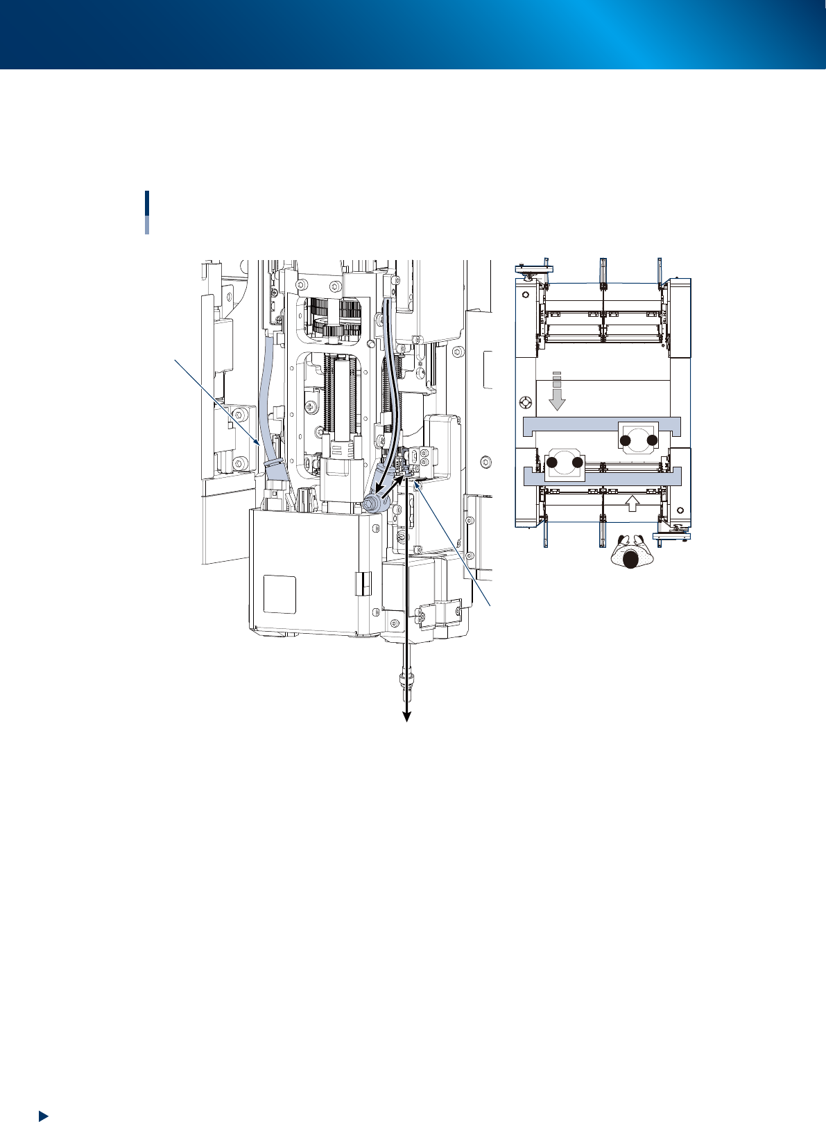
Blow air path on RS head unit
Seen RS head unit from front, the air hose on the right is called "Rod 1 air line". The other side is called
"Rod 2 air line". When using blow air for RS head maintenance, select a rod based on checking the
head unit to be maintained, worker's position, and rod position.
Positions of head unit and rod
Example: Head unit B
Rod 1 air line
Rod 2 side
1
2
1
2
B
A
Move head unit.
↓ Machine front
533J0-KMX-00
8. Others
3-71
Chapter 3 Periodic maintenance items
8
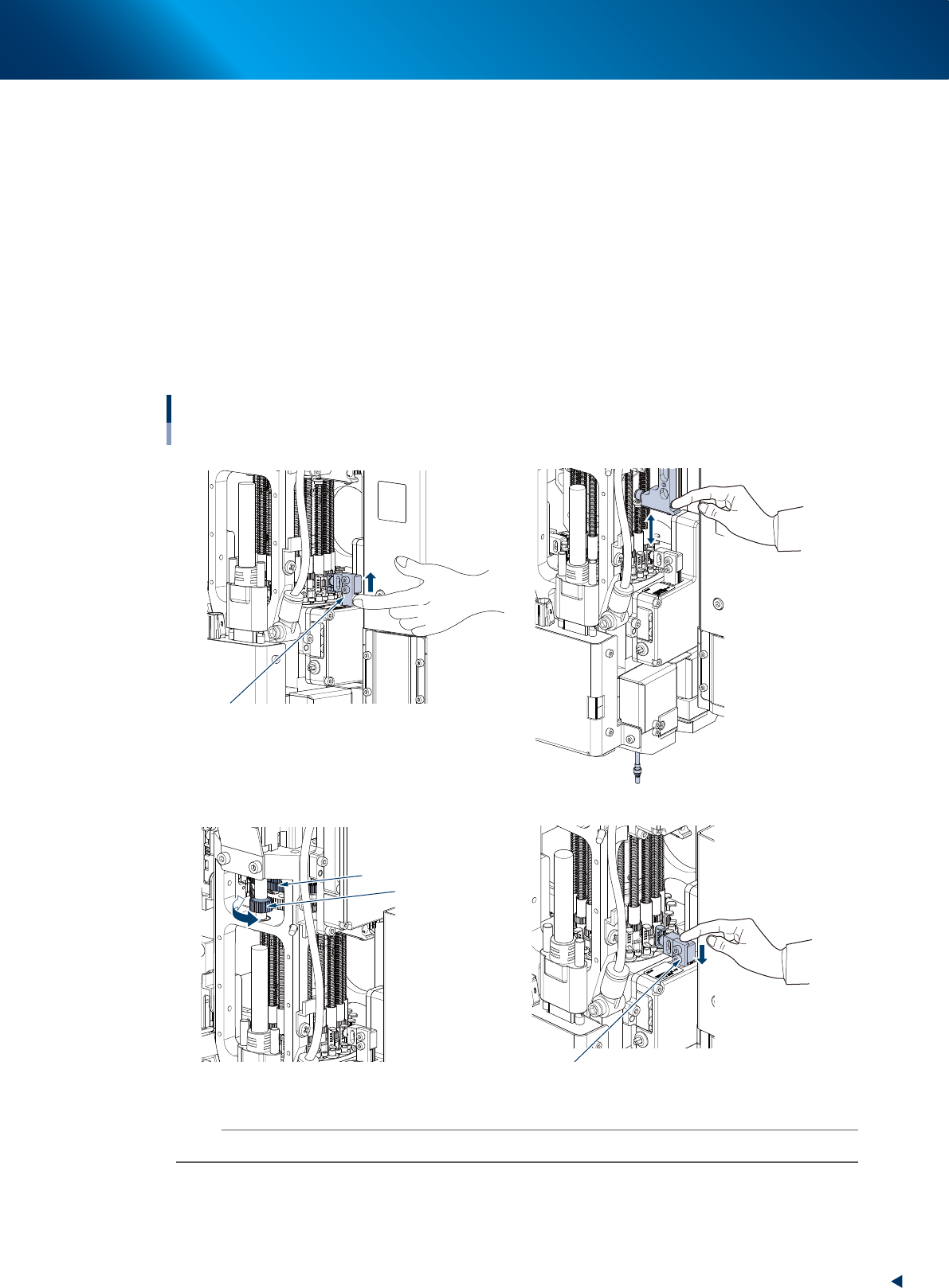
Blow inside the shaft as follows:
1. Raise the target rod side of V-axis, then the target spool raises and blows with high pressure
inside the nozzle shaft.
2. Keep this condition and push Z-axis on its target rod for some times using finger to move
vertically the nozzle shaft installed in its lower area.
3. Hold N-axis gear by hand and turn R-axis gear, then rotate the nozzle shaft approximately 120
degrees.
4. Keep this condition and push Z-axis on its target rod for some times using finger to move
vertically the nozzle shaft installed in its lower area.
5. Repeat the procedures above 3 and 4.
6. Lower V-axis using finger to stop high pressure blow.
7. Turn N-axis to rotate the rotary, then repeat the procedures of 1 to 6 for all the heads.
High pressure blow inside of nozzle shaft
Lower V-axis to stop high pressure blow
Turn R-axis gear
Hold N-axis gear by hand
Raise V-axis to blow with high pressure
1
8- 28-
3
8-
6
8-
4
8-
533J2-KMX-00
n
NOTE
It requires approx. 30 seconds to blow per head. If dirt cannot be removed, blow a little longer.
8. Others
3-72
Chapter 3 Periodic maintenance items
9
Turn ON (0 to 1) the "Head shaft blow"
valve and OFF (1 to 0) the "Head
vacuum switch" for the head unit
cleaned, by the procedure of Step 7.
0
Attach the filter.
1. Attach new filters to all heads referring to
Chapter 3, "2.4.1 Inspecting and replacing
the air filters".
2. Retrieve the square cloth after completing
your work.
q
Check the vacuum level in condition
without the nozzle and filter.
• Reference value of vacuum level: 140 or
less
If the vacuum level is out of the value,
perform Step 5 to 10 again for relevant nozzle
shaft.
TIP
See Chapter 2, "RM head" of "How to check for clogged
nozzles (on the [Unit]-[Head] tab screen)" for checking
method of vacuum level.
w
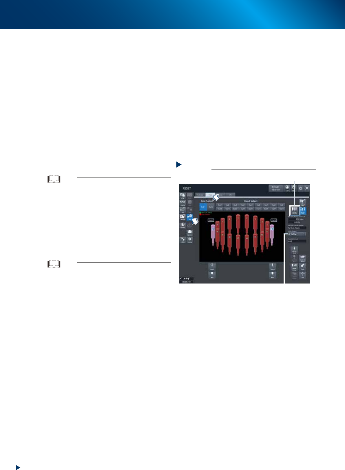
wReturn spools to original position.
1. Close the machine cover and set carriage.
2. Release the emergency stop.
3. Open [Unit] - [Head] screen.
4. Select the table to perform the work.
5. Pressing [Recover Valve Pos] returns spools
to the reset positions.
TIP
The [Recover Valve Pos] is a vacuum position.
Recovering valve position
Step 12
[Recover Valve Pos] button
Table Select
54329-KMX-00