YRM20_Mainte_E.pdf - 第170页
1. Specifications ap-3 Appendix 1.3 Connection between machines T o exc hange signals such as board request and operation status with the downstream or upstream mac hine, the "NEXT INTERF A CE" and "PREVIOU…
1. Specifications
ap-2
Appendix
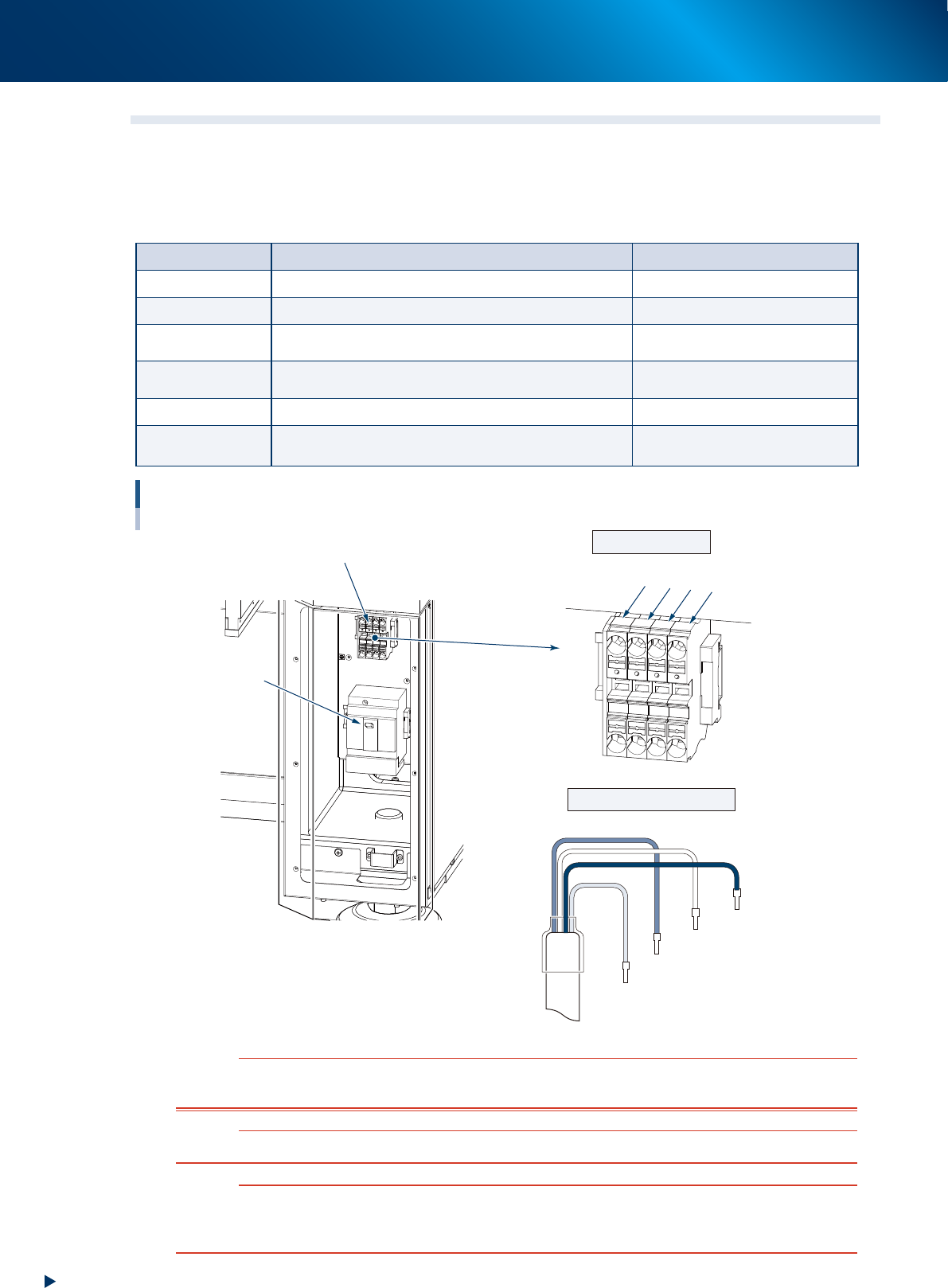
1.2 Power connection terminals
The power connection terminals are located inside the front lower panel of the machine. Connect the power
cables shown below to the primary side terminals L1, L2, L3 of main breaker and ground terminal on the
main machine.
►
Puwer supply specifications
Item Specification Remarks
Power supply 3-phase AC 200/208/220/240/380/400/416V +/-10%
Frequency 50 / 60Hz
Power capacity 2.5kVA (Peak 5.4kVA)
5.4 kVA is the value when X and Y
axes move at full speed.
Breaker rating 30A
Includes the inrush current of the
transformer.
Maximum current 55A
When 200V power is supplied.
Average power
consumption
2.2kW
Power connection terminals
Front left lower part of machine
Terminal block
Main breaker
L1 (Red)
L1
L2
L3
PE
L3 (Black)
L2 (White)
PE (Green)
Power input termials
Example of cable arrangement
53A02-KMX-00
w
WARNING
TO AVOID THE RISK OF ELECTRICAL SHOCK, MAKE SURE THAT THE POWER SOURCE IS OFF BEFORE CONNECTING THE
POWER CABLE. ALSO MAKE SURE THAT THE GROUND CABLE IS SECURELY CONNECTED TO THE MACHINE.
c
CAUTION
Use a power cable whose conductor cross-section area is greater than 6.0mm
2
.
c
CAUTION
By referring to the figure above, be sure to connect the power cable correctly to the L1, L2 and L3 terminals on the power
input terminal block so that they are in the normal phase. Incorrect connection may cause the vacuum pump to turn in the
wrong direction and drastically damage to the components in the vacuum pump.
1. Specifications
ap-3
Appendix
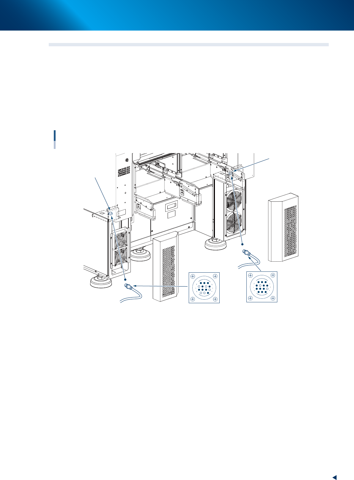
1.3 Connection between machines
To exchange signals such as board request and operation status with the downstream or upstream machine,
the "NEXT INTERFACE" and "PREVIOUS INTERFACE" connectors located on the rear of the machine are
used.
The "NEXT INTERFACE" connector connects to the downstream machine, and the "PREVIOUS INTERFACE"
connector connects to the upstream machine such as a loader.
At the standard "R to L" flow line, the PREVIOUS INTERFACE is located on the observer's left and the NEXT
INTERFACE on the right.
Both connectors use AMP206043-1 (14 pin, receptacle).
Connection between machines
NEXT
INTERFACE connector
INTERFACE connector
PREVIOUS
AMP 206043-1
(14-pin receptacle)
AMP 206043-1
(14-pin receptacle)
14
11
12
7
4
8
1
3
14
11
12
7
8
3
1
4
53A03-KMX-00
1. Specifications
ap-4
Appendix
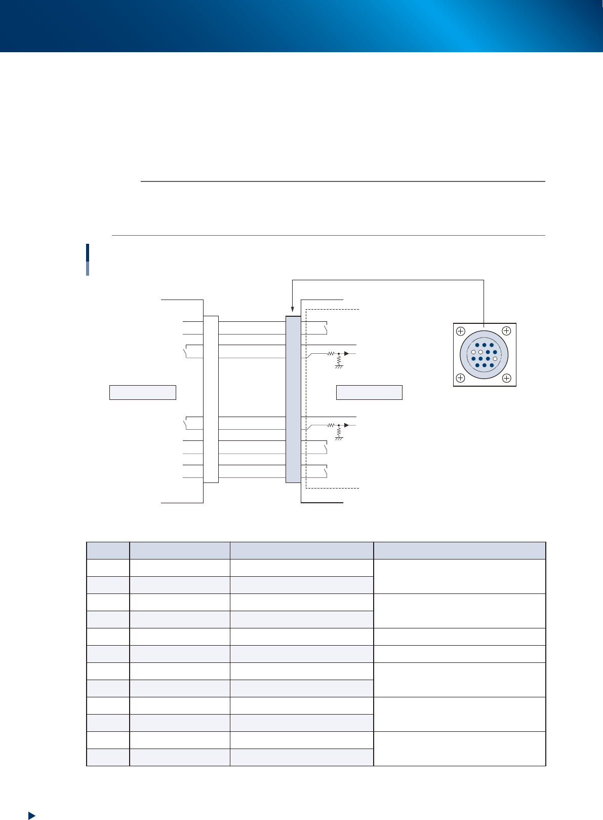
1.3.1 PREVIOUS INTERFACE
When the following three conditions are met, the PREVIOUS INTERFACE circuit in the machine allows the
next board to be carried in.
1. Machine is ready for carrying in a board (BUSY OUT: ON)
2. Board carry-in signal is input from the upstream (previous process) machine. (BA IN : ON)
3. Automatic operation signal is input from the upstream (previous process) machine. (UR IN : ON)
n
NOTE
• When the automatic operation signal (UR IN) from the loader turns off during transfer of a board, the machine
temporarily stops carrying in the board.
• When the board being carried in is detected by the entrance sensor, the BUSY OUT signal turns off.
• Carrying in the board is finished when both the BUSY OUT and BA IN turn off.
1
2
3
4
5
6
7
8
9
10
11
12
13
14
7
12
4
8
1
14
11
3
PREVIOUS INTERFACE circuit
AMP 206043-1
(14-pin receptacle)
Signal input during
board carry-in
Signal output to request
board carry-out
Signal output during
automatic operation
Signal input during
automatic operation
Signal input during waiting for
board between machines
BUSY OUT
LR OUT
UR IN
BA IN
LE OUT
I/O BOARD
+24V
+24V
This machineUpstream
PREVIOUS INTERFACE
53A04-KMX-00
►
Board transfer signal specifications (PREVIOUS INTERFACE)
Pin No. Signal name I/O specifications Signal specifications
1 BUSY OUT Relay contact (zero voltage) output
Signal output during board carry-in
2 BUSY OUT Relay contact (zero voltage) output
3 +24V Input common (+24V)
Signal input of board carry-out request
4 BA IN Voltage input
5 NC (with dummy pins) (Prevents misinsertion)
6~8 NC
9 +24V Input common (+24V)
Signal input during automatic operation
10 UR IN Voltage input
11 LR OUT Relay contact (zero voltage) output
Signal output during automatic operation
12 LR OUT Relay contact (zero voltage) output
13 LE OUT Relay contact (zero voltage) output
Signal output during waiting for board between
machines
14 LE OUT Relay contact (zero voltage) output