YRM20_Mainte_E.pdf - 第172页
1. Specifications ap-5 Appendix 1.3.2 NEXT INTERF ACE When the following three conditions are met, the NEXT INTERF ACE circuit in the mac hine allows the board to be carried out. 1. Machine is ready for carr ying out the …
1. Specifications
ap-4
Appendix
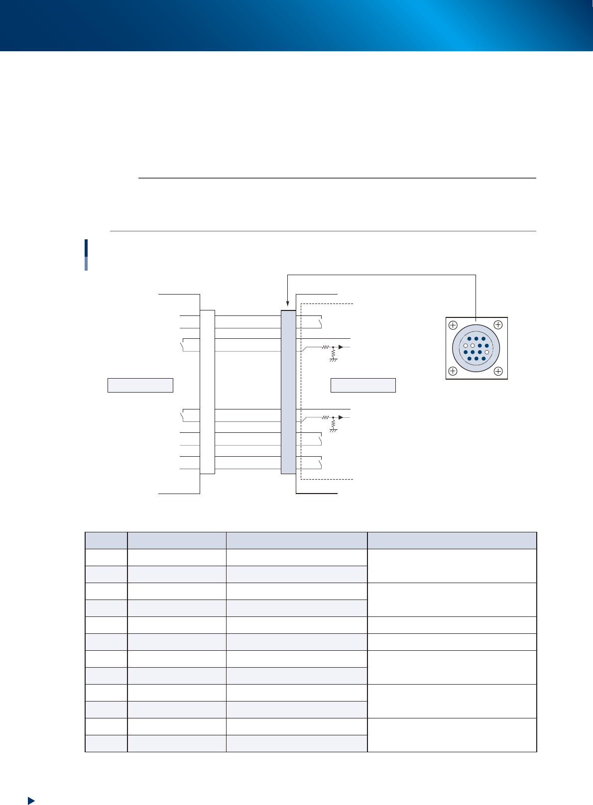
1.3.1 PREVIOUS INTERFACE
When the following three conditions are met, the PREVIOUS INTERFACE circuit in the machine allows the
next board to be carried in.
1. Machine is ready for carrying in a board (BUSY OUT: ON)
2. Board carry-in signal is input from the upstream (previous process) machine. (BA IN : ON)
3. Automatic operation signal is input from the upstream (previous process) machine. (UR IN : ON)
n
NOTE
• When the automatic operation signal (UR IN) from the loader turns off during transfer of a board, the machine
temporarily stops carrying in the board.
• When the board being carried in is detected by the entrance sensor, the BUSY OUT signal turns off.
• Carrying in the board is finished when both the BUSY OUT and BA IN turn off.
1
2
3
4
5
6
7
8
9
10
11
12
13
14
7
12
4
8
1
14
11
3
PREVIOUS INTERFACE circuit
AMP 206043-1
(14-pin receptacle)
Signal input during
board carry-in
Signal output to request
board carry-out
Signal output during
automatic operation
Signal input during
automatic operation
Signal input during waiting for
board between machines
BUSY OUT
LR OUT
UR IN
BA IN
LE OUT
I/O BOARD
+24V
+24V
This machineUpstream
PREVIOUS INTERFACE
53A04-KMX-00
►
Board transfer signal specifications (PREVIOUS INTERFACE)
Pin No. Signal name I/O specifications Signal specifications
1 BUSY OUT Relay contact (zero voltage) output
Signal output during board carry-in
2 BUSY OUT Relay contact (zero voltage) output
3 +24V Input common (+24V)
Signal input of board carry-out request
4 BA IN Voltage input
5 NC (with dummy pins) (Prevents misinsertion)
6~8 NC
9 +24V Input common (+24V)
Signal input during automatic operation
10 UR IN Voltage input
11 LR OUT Relay contact (zero voltage) output
Signal output during automatic operation
12 LR OUT Relay contact (zero voltage) output
13 LE OUT Relay contact (zero voltage) output
Signal output during waiting for board between
machines
14 LE OUT Relay contact (zero voltage) output
1. Specifications
ap-5
Appendix
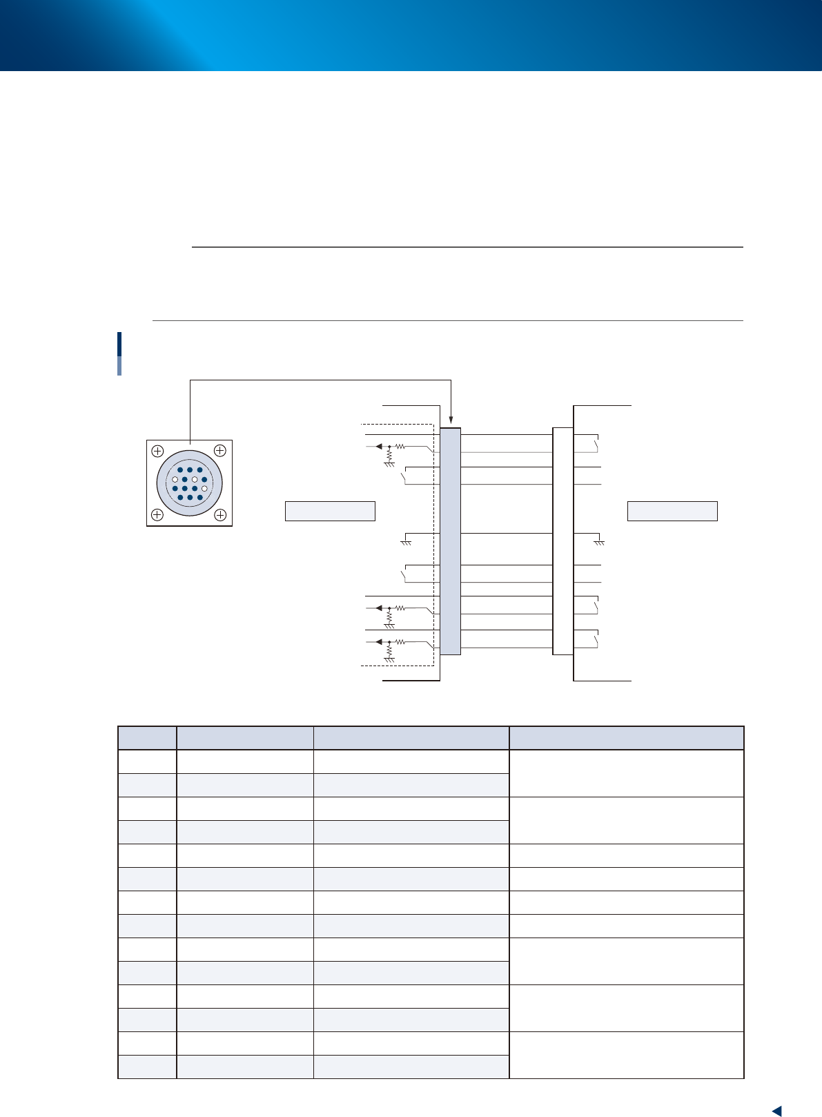
1.3.2 NEXT INTERFACE
When the following three conditions are met, the NEXT INTERFACE circuit in the machine allows the board
to be carried out.
1. Machine is ready for carrying out the board (BA OUT: ON)
2. Board carry-in signal is input from the downstream machine. (BUSY IN : ON)
3. Automatic operation signal is input from the downstream machine. (LR IN : ON)
n
NOTE
• When the automatic operation signal (LR IN) from the downstream machine turns off during transfer of a board, the
machine stops temporarily carrying out the PC.
• When the board being carried out is detected by the exit sensor, the BA OUT signal turns off.
• Carrying out the board is finished when both the BUSY IN and BA OUT turn off.
1
2
3
4
5
6
7
8
9
10
11
12
13
14
7
12
4
8
1
14
11
3
NEXT INTERFACE Circuit
AMP 206043-1
(14-pin receptacle)
BUSY IN
+24V
+24V
UR OUT
LR IN
+24V
LE IN
BA OUT
Signal output during
board carry-in
Signal input to request
board carry-out
Signal input during
automatic operation
Signal output during
automatic operation
Signal output during waiting for
board between machines
I/O BOARD
GND GND
This machine Downstream
NEXT INTERFACE
53A05-KMX-00
►
Board transfer signal specifications (NEXT INTERFACE)
Pin No. Signal name I/O specifications Signal specifications
1 +24V Input common (+24V)
Signal input during board carry-in
2 BUSY IN Voltage input
3 BA OUT Relay contact (zero voltage) output
Signal output to request board carry-out
4 BA OUT Relay contact (zero voltage) output
5 NC
6 NC (with dummy pins) (Prevents misinsertion)
7 GND
8 NC
9 UR OUT Relay contact (zero voltage) output
Signal output during automatic operation
10 UR OUT Relay contact (zero voltage) output
11 +24V Input common (+24V)
Signal input during automatic operation
12 LR IN Voltage input
13 +24V Input common (+24V)
Signal input during waiting for board between
machines
14 LE IN Voltage input
2. YAMAHA Service website for user
ap-6
Appendix
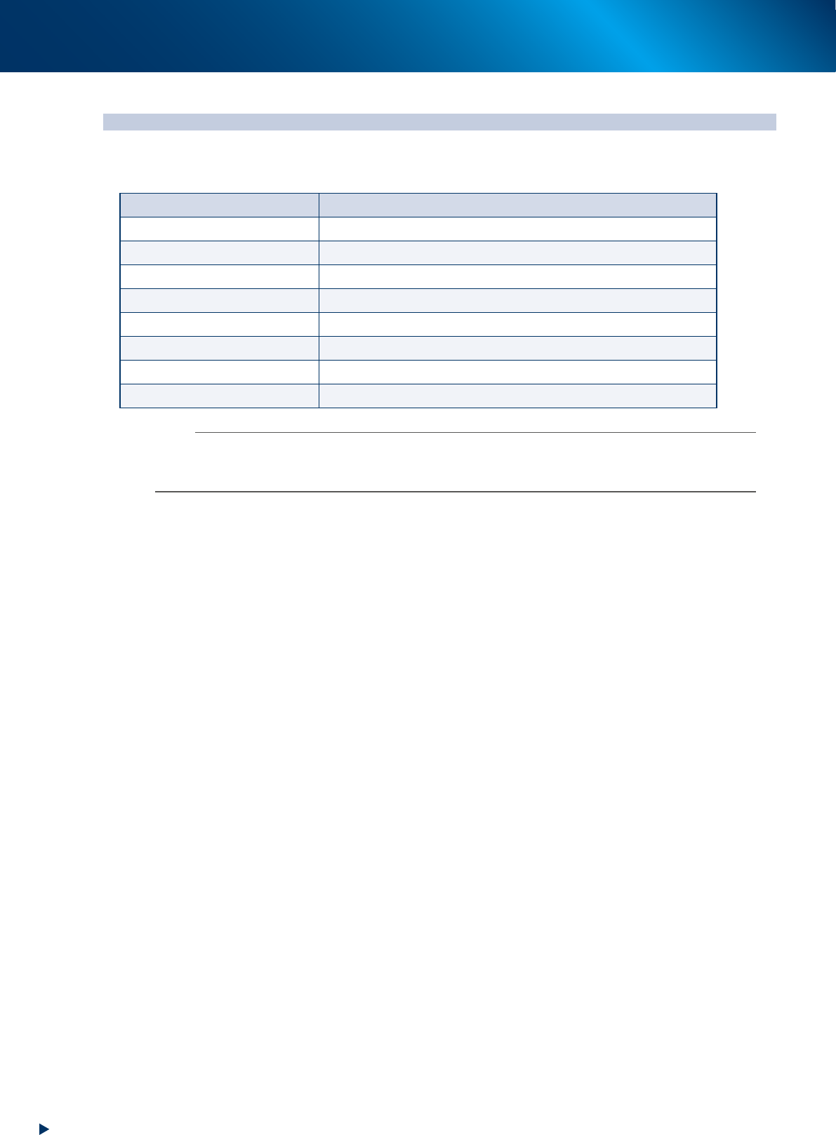
2. YAMAHA Service website for user
Our service information can be obtained through the Service Website. The following contents can be
available for example.
Item Contents
Important notification New/corrected service information
Manual download Download the operation/maintenance manuals
Support items Introduction of the list of maintenance tools, etc.
Training Informations about periodical training schedule
Vision recognition Recognition information of special parts such as coils
Troubleshooting Supporting informations for trouble solutions
Circuit/air path diagram Materials for investigation about the electrical troubles
Maintenance parts list List of maintenance target parts
n
NOTE
The user registration is necessary for using our Service website. The electronic certification and the first time password are
provided upon completing your registration.
Contact your sales representative for the detail of user registration.