YRM20_Mainte_E.pdf - 第173页
2. Y AMAHA Service website for user ap-6 Appendix 2. Y AMAHA Ser vice website for user Our service information can be obtained through the Service W ebsite. The following contents can be available for example. Item Conte…
1. Specifications
ap-5
Appendix
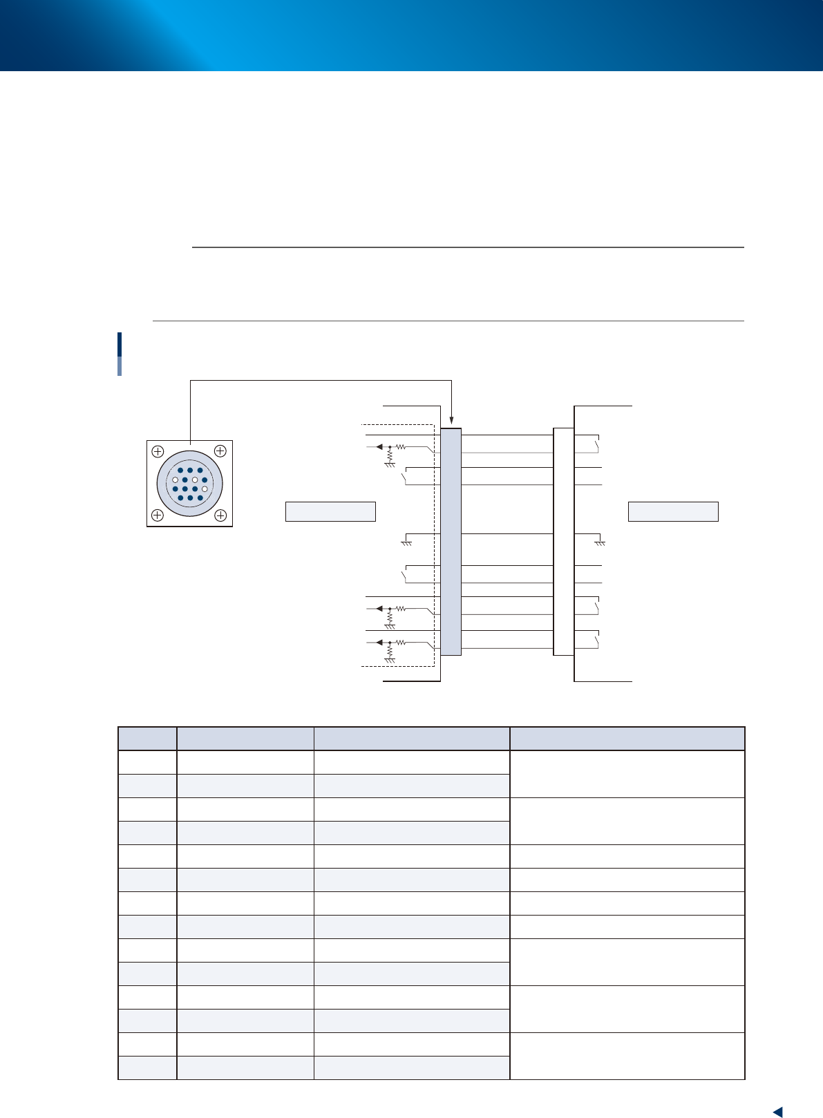
1.3.2 NEXT INTERFACE
When the following three conditions are met, the NEXT INTERFACE circuit in the machine allows the board
to be carried out.
1. Machine is ready for carrying out the board (BA OUT: ON)
2. Board carry-in signal is input from the downstream machine. (BUSY IN : ON)
3. Automatic operation signal is input from the downstream machine. (LR IN : ON)
n
NOTE
• When the automatic operation signal (LR IN) from the downstream machine turns off during transfer of a board, the
machine stops temporarily carrying out the PC.
• When the board being carried out is detected by the exit sensor, the BA OUT signal turns off.
• Carrying out the board is finished when both the BUSY IN and BA OUT turn off.
1
2
3
4
5
6
7
8
9
10
11
12
13
14
7
12
4
8
1
14
11
3
NEXT INTERFACE Circuit
AMP 206043-1
(14-pin receptacle)
BUSY IN
+24V
+24V
UR OUT
LR IN
+24V
LE IN
BA OUT
Signal output during
board carry-in
Signal input to request
board carry-out
Signal input during
automatic operation
Signal output during
automatic operation
Signal output during waiting for
board between machines
I/O BOARD
GND GND
This machine Downstream
NEXT INTERFACE
53A05-KMX-00
►
Board transfer signal specifications (NEXT INTERFACE)
Pin No. Signal name I/O specifications Signal specifications
1 +24V Input common (+24V)
Signal input during board carry-in
2 BUSY IN Voltage input
3 BA OUT Relay contact (zero voltage) output
Signal output to request board carry-out
4 BA OUT Relay contact (zero voltage) output
5 NC
6 NC (with dummy pins) (Prevents misinsertion)
7 GND
8 NC
9 UR OUT Relay contact (zero voltage) output
Signal output during automatic operation
10 UR OUT Relay contact (zero voltage) output
11 +24V Input common (+24V)
Signal input during automatic operation
12 LR IN Voltage input
13 +24V Input common (+24V)
Signal input during waiting for board between
machines
14 LE IN Voltage input
2. YAMAHA Service website for user
ap-6
Appendix
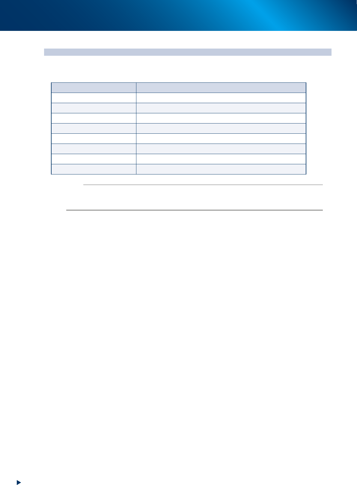
2. YAMAHA Service website for user
Our service information can be obtained through the Service Website. The following contents can be
available for example.
Item Contents
Important notification New/corrected service information
Manual download Download the operation/maintenance manuals
Support items Introduction of the list of maintenance tools, etc.
Training Informations about periodical training schedule
Vision recognition Recognition information of special parts such as coils
Troubleshooting Supporting informations for trouble solutions
Circuit/air path diagram Materials for investigation about the electrical troubles
Maintenance parts list List of maintenance target parts
n
NOTE
The user registration is necessary for using our Service website. The electronic certification and the first time password are
provided upon completing your registration.
Contact your sales representative for the detail of user registration.
3. Maintenance parts
ap-7
Appendix
3. Maintenance parts
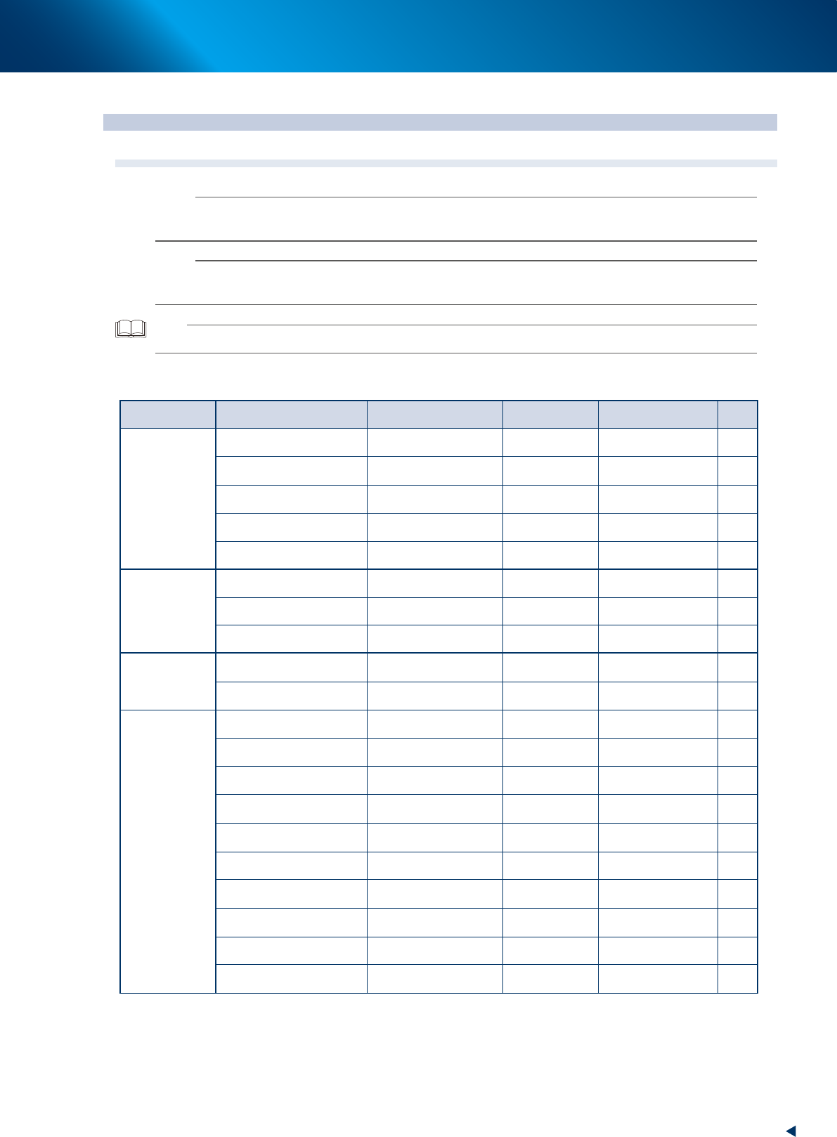
3.1 YRM20 consumable parts list
n
NOTE
The parts (Part Nos.) in this manual are at the time of issuing this manual. The Part Nos. may be changed without prior
notice. Make sure to verify the latest Part Nos. before ordering.
n
NOTE
• The consumable part positions and the replacement procedure are described in this manual.
• See "2.1.3 Common to all models" in chapter 1 for nozzle consumable parts.
TIP
When there are consumable parts of assembly parts and individual parts, the later is written in parenthesis
►
Consumable parts list
Position Name Part name Part No. Note Qty
HM head unit
Nozzle leaf spring LEAF SPRING KG7-M7137-A0X 20
*1
Leaf spring for strengthening
nozzle holding force
PLATE, SPRING KLW-M714W-00X 20
*1
Mounting screw for nozzle leaf
spring
SCREW, PAN HEAD 90990-08J016 20
*1
Ejector filter FILTER KLW-M8527-00X 10
*1
Gasket for filter GASKET KLW-M715B-00X 10
*1
RM head unit
Single air filter FILTER KMB-M7070-00X 1 pcs 18
*1
Air filter of 20 pieces FILTER, 20PCS KMB-M3856-00X 20 pcs
-
Air filter of 1000 pieces FILTER, 1000PCS KMB-M3857-01X 1000 pcs
-
Conveyor belt
Entrance/Exit (CV1, CV4) BELT, CONVEYOR KMX-M917H-00X
Length : 646mm
Width : 6mm
4
Stage 1 and 2 (CV2, CV3) BELT, CONVEYOR KMX-M9110-00X
Length : 1170mm
Width : 6mm
4
Base
Air filter element FILTER ELEMENT KLF-M8502-50X Air filter (Media) 1
Mist filter element MIST FILTER ELEMENT KLF-M8502-70X Mist filter (Media) 1
Fan filter for upper surface FILTER, FAN KMK-M131M-00X
Installed at 4 positions
on upper surface
4
Fan filter for rear side of base FILTER, TOP COVER FAN KLF-M130J-00X
Installed at left back of
machine
1
Air intake filter FILTER,Y FAN KMX-M13NE-00X
Installed at 4 positions,
front and rear
4
Filter for control box (front) MEDIA FILTER KME-M53A9-00X 1
Filter for control box (lateral
side)
MEDIA FILTER KME-M53A9-10X 1
Vacuum pump assembly VACUUM PUMP SUB ASSY KMX-M85AA-00X
Vacuum pump assembly
for RM head unit
1
*1
Vacuum pump PUMP,VACUUM KMX-M8501-00 Single vacuum pump (1)
*1
Pump filter element FILTER,VAC.PUMP KMX-M8611-00
Filter element for above
vacuum pump
(1)
*1
*1
Required quantity per one head unit