YRM20_Mainte_E.pdf - 第91页
3. 3-month maintenance items 3-24 Chapter 3 Periodic maintenance items 3.1.2 Check the ejector vacuum level T his section chec ks the ejector vacuum level of eac h head. When it cannot reach the specified v acuum level, …
3. 3-month maintenance items
3-23
Chapter 3 Periodic maintenance items
3. 3-month maintenance items
This section describes 3-month maintenance items.
3.1 HM head unit
3.1.1 Cleaning/replacing the air filter
The filters should generally be inspected about every 3 months, although this depends on the supply air
condition and the operating time. If the filter is contaminated slightly, it can be cleaned by using an air blow
tool. Replacing the filter is recommended when it can no longer be adquately cleaned by air blowing.
1
Move the head unit.
1. Remove all items sensitive to magnetic fields
such as wristwatches and magnetic ID cards.
e
2. Press the emergency stop button and detach
the feeder exchange carriage, then open the
machine safety cover.
3. Move the head unit to convenient position to
work.
4. Place a square cloth under the head unit.
2
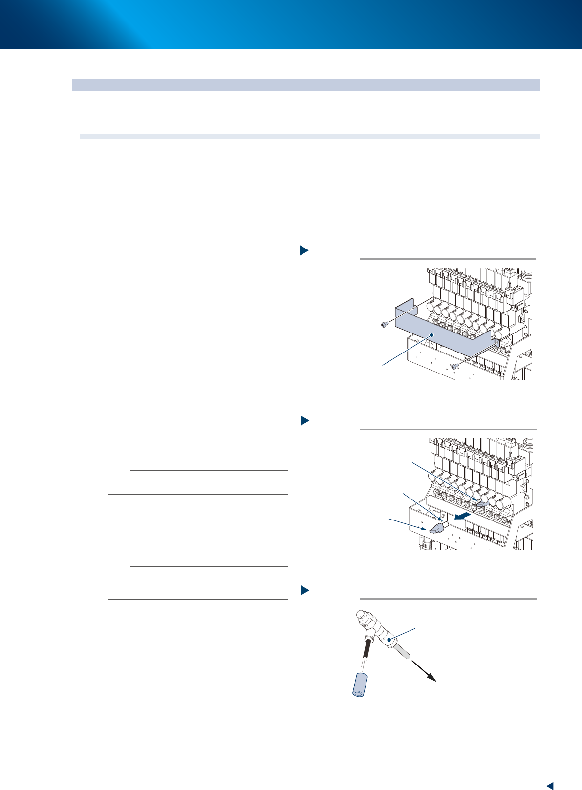
Remove the current plate shown in the
figure right using Phillips screwdriver.
3
Remove the filter cap and the filter by
rotating them counterclockwise
4
Clean the filter by the air blow tool
when the filter is only lightly
contaminated, and it can be reused.
n
NOTE
If there are heavy dust deposits in the filter or the filter has
discolored, replace it with a new filter (KLW-M8527-00X).
5
Attach the filter.
1. Attach the filter to the filter cap.
2. Place the filter to its original position and
rotate it clockwise to fix it.
n
NOTE
Check the gasket (KLW-M715B-00X) condition upon
attaching the filter. When it is worn or distorted, replace it
with a new one.
6
Attach the current plate.
1. Attach the current plate to its original
position using Phillips screwdriver.
2. Retrieve a square cloth.
Removing the current plate
Step 2
Current plate
53330-KMX-00
Removing the filter cap
Step 3
Filter cap
Filter
Pull out by rotating counterclockwise
53331-KMX-00
Cleaning the filter
Step 4
Filter
Air blow tool (option)
Connected to
the air connector of
feeder exchange carriage
53332-KMX-00
3. 3-month maintenance items
3-24
Chapter 3 Periodic maintenance items
3.1.2 Check the ejector vacuum level
This section checks the ejector vacuum level of each head.
When it cannot reach the specified vacuum level, replacement of the ejector bit or the valve may be
required. Perform the replacement referring to "6.1.1 Replacement of ejector bit" in Chapter 3, or to "3.1
HM head: Replacing the valves" in Chapter 5.
1
Move the head unit to machine front
side.
1. Remove all items sensitive to magnetic fields
such as wristwatches and magnetic ID cards.
e
2. Press the emergency button and detach the
feeder exchange carriage on the side to
which an engineer puts his/her body to
perform maintenance work. Then open the
machine safety cover.
3. Move the head unit to convenient position to
wrok.
4. Place a square cloth under the head unit.
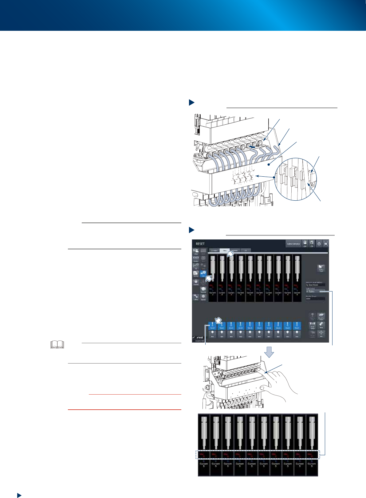
2
Disconnect all the air hoses from the
upper joints. Keep the lower joints being
connected.
n
NOTE
The air hoses are attached to the holder located at the
reverse side of head unit fromt cover. Upon disconnecting
the air hoses, be careful not to drop off the hoses from
holder.
3
Check the vacuum level of each head.
1. Open the [Unit] - [Head] screen.
2. Select any head unit at the "Select Table"
field.
3. Press the [Vacuum] button of all heads.
4. Close the air joint part with finger.
5. The vacuum level of sealed head appears at
the "Maximum value" field located at the
center of screen. Check if the value is "190"
or more, which is the measuring reference
value for sealed condition.
TIP
When the measured value cannot reach the measuring
reference value, recheck the air path (ejector/valve) of the
head and clean or replace it as necessary.
4
Attach the air hoses to their original
position.
c
CAUTION
Insert the air hoses all the way seated and confirm that
they do not drop off.
Disconnecting air hoses
Step 2
Air hose
Removed air hose
Holder
Air joint
Head unit
front cover
53397-KMX-00
Checking the vacuum level
Step 3
[Vacuum] button
Check the maximum
value of vacuum level
Close the air joint section
with finger
Table Select
54312-KMX-00
3. 3-month maintenance items
3-25
Chapter 3 Periodic maintenance items
3.1.3 Checking the operation of each valve of head
This section describes the procedure of checking the operation of the blow valve and the cleaning blow
valve of head unit. The head unit is installed 2 types of valves, one is the blow valve blowing by each
shingle head, and the other is the cleaning blow valve blowing powerfully to clean up inside of shaft.
When the valve motion error occurs, it needs to be replaced. See Chapter 5, "3.1 HM head: Replacing the
valves"
c
CAUTION
The cleaning blow exhausts powerful air. The nozzle attached to the head should be detached upon performing the
cleaning blow. If the cleaning blow is performed with the nozzle attached, the nozzle may drop off from head and may be
damaged or lost.
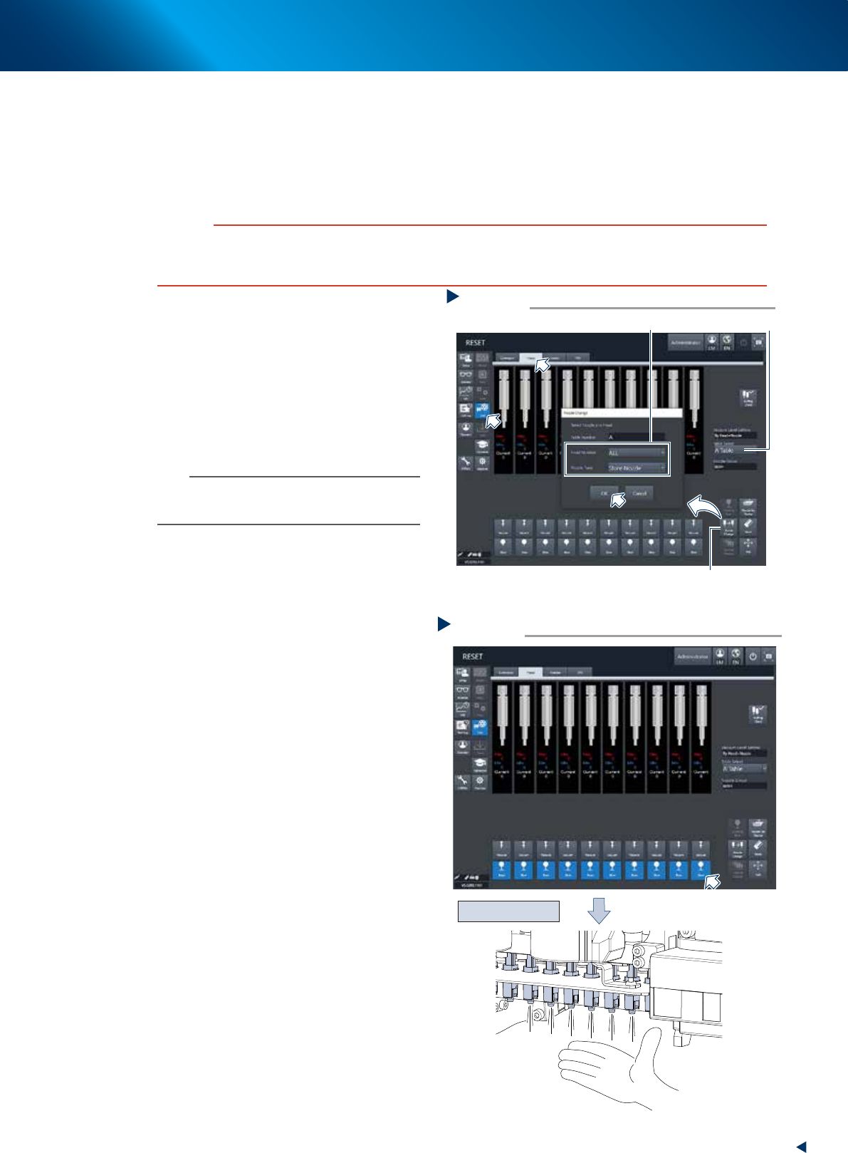
1
Detach all the nozzles from the heads.
When the nozzle station is equipped.
1. Open the [Unit] - [Head] screen.
2. Select any head unit from "Table Select".
3. Press the [Nozzle Change] button. Select
"ALL" for "Head Number" and select "Store
Nozzle" for "Nozzle Type" on the "Nozzle
Change" screen.
4. Press the [OK] button to return all nozzles to
the nozzle station.
n
NOTE
When the machine does not equip the nozzle station,
open the machine safety cover and detach the nozzles by
hand.
e
2
Move the head unit to machine front
side.
1. Press the emergency stop button and detach
the feeder exchange carriage.
2. Open the machine safety cover and move
the head unit to convenient position to work.
3
Blow each head by opening the [Unit]
- [Head] screen and pressing the [Blow]
buttons of all the heads.
4
Check the condition of blowing by
placing your hand beneath the each
head to check that all the heads exhaust
air evenly. When a head exhausts less air
than the others or does not, the valve
replacement is required. See "3.1
HM head: Replacing the valves" in
Chapter 5 to replace the valve.
Storing nozzle
Step 1
Select “ALL” for Head Number, “Store Nozzle”for Nozzle Type
[Nozzle Change] button
Table Select
54313-KMX-00
Checking the blow operation
Step 3,4
Press the [Blow] button of each head
Check the air blow
54314-KMX-00