YRM20_Mainte_E.pdf - 第97页
3. 3-month maintenance items 3-30 Chapter 3 Periodic maintenance items 3.2 RM head unit 3.2.1 Inspecting/cleaning nozzle shaft tip T he dirt on nozzle tip may cause shaft oper ation error or nozzle change error . T heref…
3. 3-month maintenance items
3-29
Chapter 3 Periodic maintenance items
3.1.7 Applying grease to spline shaft
█
Perform this procedure as necessary.
Basically, it is not necessary to apply grease to spline shaft (Z-axis) of HN head unit. However, if
touching the shaft surface or solvent sprayed on it, the grease is removed and rust may appear.
Slightly apply specified grease (NSL) for anti-rust as needed.
1
Move the head unit.
e
1. Press the emergency stop button and detach
the feeder exchange carriage.
2. Open the machine safety cover and move
the head unit to convenient position to work.
2
Clean the spline shaft using a lint-free
cloth or cotton swab.
3
Apply grease to the spline shaft by
spreading thinly the specified grease
(NSL) with finger uniformly over the
shaft surface.
4
Wipe off the excess grease.
1. Move up/down the spline shaft several times
by hand.
2. Wipe off excess grease on top and bottom
of the spline shaft with lint-free cloth or
cotton swab.
c
CAUTION
Make sure not to wipe off grease on spline shaft surface
completely.
Applying grease to the spline shaft
Step 3
Apply uniformly
53335-KMX-00
3. 3-month maintenance items
3-30
Chapter 3 Periodic maintenance items
3.2 RM head unit
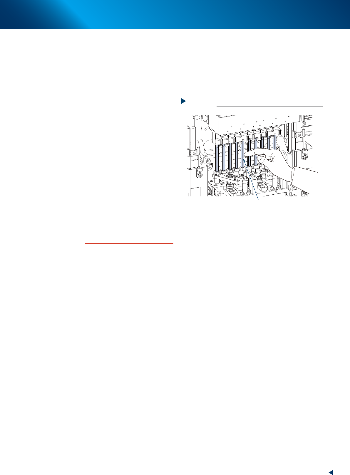
3.2.1 Inspecting/cleaning nozzle shaft tip
The dirt on nozzle tip may cause shaft operation error or nozzle change error. Therefore, perform visual
inspection and cleaning of shaft tip once every 3 months.
1
Prepare for work.
e
1. Remove all items sensitive to magnetic fields such as wristwatches and magnetic ID cards.
2. If the machine is equipped with nozzle station, store all nozzles to the nozzle station.
3. Press the emergency stop button, detach the feeder exchange carriage, then open the machine safety cover.
4. Move the head unit to convenient position to work and place a square cloth under the head unit.
n
NOTE
See "Lowering RM head/nozzle shafts" above for details of the lowering RM head nozzle shaft.
2
Inspect shaft tip.
1. Turn the rotary so that the relevant nozzle
shaft locates under the Z-axis.
2. Press the Z-axis with finger to lower the
nozzle shaft.
3. (When the nozzle station is not equipped)
Detach nozzle manually.
4. Check that no dirt is found on the position
shown at right.
TIP
Check the inside of shaft with a hand mirror or the similar.
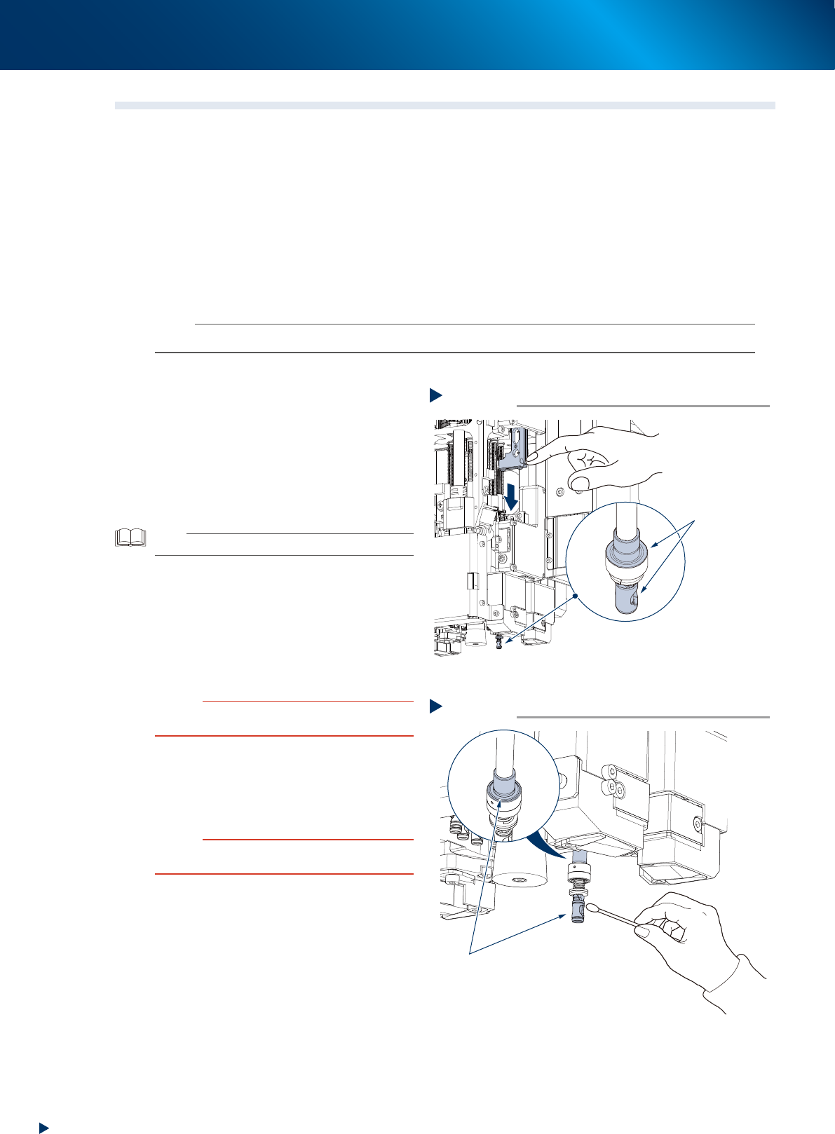
3
Clean nozzle shaft tip.
1. Lower the nozzle shaft with the same
procedure as Step 2.
2. Wipe off dirt on nozzle shaft tip with cotton
swab.
Apply small amount of ethanol on cotton
swab for heavy dirt.
c
CAUTION
Return the nozzle shaft slowly after it is lowered by hand,
as the nozzle shaft tends to strike upon returning.
4
Inspect/clean rest of nozzle tips.
1. Inspect/clean rest of nozzle tips with the
same procedures as Step 2 to 3.
2. Retrieve a square cloth after working.
c
CAUTION
Make sure that all nozzle shafts are completely raised up
after they returned.
5
Return the nozzles to their removed
positions if they are removed by hand
from heads.
Step2
Inspecting shaft tip
Check here
visually
Press the Z-axis
with finger to lower
the nozzle shaft
53340-KMX-10
Step3
Cleaning shaft tip
Clean here
533F5-KMX-10
3. 3-month maintenance items
3-31
Chapter 3 Periodic maintenance items
3.3 PU-axis
PU-axis (push up axis) takes an essential role which prevents board warpage upon clamping a board and
board sinking upon transferring.
Moreover, PU-axis functions as preventing mounting accuracy offset caused by the board sinking upon
transferring. So the periodical inspecting/cleaning should be performed to maintain its function.
c
CAUTION
When the PU-axis related trouble occurs, then contact your sales representative. Disassembly and cleaning of the PU-axis
by the user will void the warranty.
3.3.1 Cleaning/lubricating PU-axis ball screw
1
Prepare for work.
1. Remove all items sensitive to magnetic fields
such as wristwatches and magnetic ID cards.
2. Read any board data.
TIP
Moving the push up unit of both stage 1 and stage 2 are
available by reading board data.
2
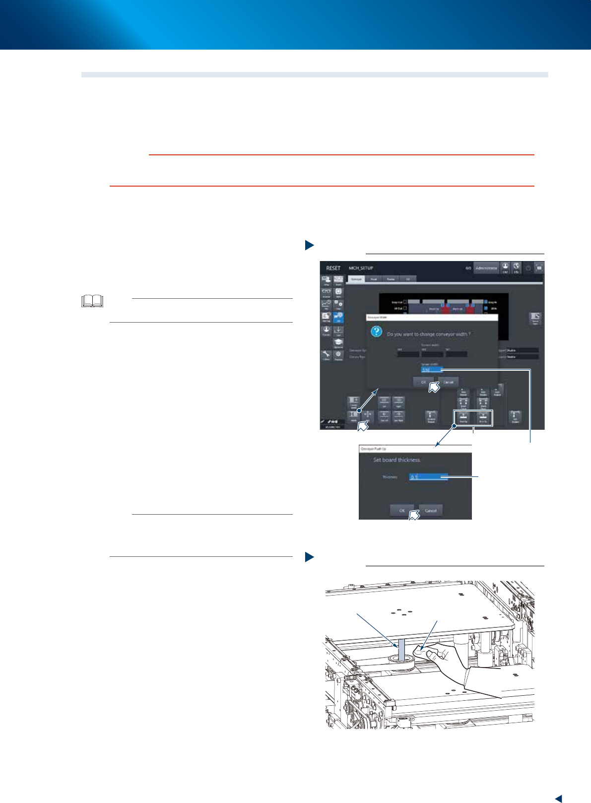
Maximize the conveyor width.
1. Press the [Width] button on the [Unit] -
[Conveyor] screen to display the [Conveyor
Width] screen.
2. Input the maximum width (510mm) of your
machine in the "Target Width" field and
press the [OK] button. Then the conveyor
width is changed to the specified.
3
Raise the push up unit.
1. Press the [Push up] button of the target stage
to display the "Conveyor Pushup" screen.
2. Input "0.1mm" in the "Board thickness" field
and press the [OK] button. Then the push up
unit raises.
n
NOTE
When the board size X of the board data selected at Step
1 excesses 380mm, the [Push up] button of upstream side
is grayed-out. The upstream push up unit raises engaging
with the raise of downstream push up unit.
e
4
Remove old grease.
1. Press the emergency stop button and detach
the feeder exchange carriage, then open the
machine safety cover.
2. Wipe away old grease completely from 2
ball screws using a lint-free cloth.
Step 2,3
2
3
Changing the conveyor width
Input 510mm
Input 0.1mm
54302-KMX-00
Cleaning ball screw
Step 4
Lint-free cloth
Ball screw
53341-KMX-00