YSM40R_Mainte_E.pdf - 第122页
3-52 3 Periodic maintenance items 4.1.4 RS head side-view camera T he RS head is equipped with a side-view camera. T he cleaning procedure for the lighting unit is described below . 1 Pr epare for work. e 1. Remove all i…
3-51
3
Periodic maintenance items
4.1.3 Side-view camera (multi-vision camera installed type)
The multi-vision camera used for the MU head and FL head machines also has a side-view camera.
The cleaning procedure for the side-view camera's lighting unit (multi-vision camera installed type) is given
below.
e
1
Prepare for work.
1. Press the emergency stop button to put
the machine in emergency stop.
2. Use the CLAMP ON/OFF switch to lower
the feeder exchange carriage and
detach it.
3. Shut off the main air supply to the
machine.
2
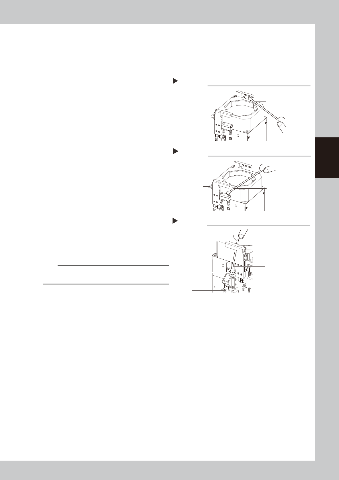
Clean the mirrors at both sides.
1. Apply a small amount of lens cleaner to
a cotton swab or lint-free cloth.
2. Lift the up/down section of the lighting
unit and clean the mirrors.
53356-N9-00
3
Clean the lighting side.
As shown in the figure at right, wipe the
lighting with a cotton swab dampened with
a small amount of lens cleaner.
53357-N9-00
4
Clean the camera side.
As shown in the figure at right, wipe the
cover with a cotton swab dampened with a
small amount of lens cleaner.
53358-N9-00
TIP
The optical brush and lens cleaner are optional
purchase items.
Cleaning the mirrors
Step 2
Grasp here and
lift upward.
Cotton swab dampened
with lens cleaner
Cleaning the lighting
Step 3
Grasp here and
lift upward.
Cotton swab dampened
with lens cleaner
Cleaning the camera side
Step 4
Clean this area
(top side).
Camera
Cotton swab dampened
with lens cleaner
3-52
3
Periodic maintenance items
4.1.4 RS head side-view camera
The RS head is equipped with a side-view camera. The cleaning procedure for the lighting unit is described
below.
1
Prepare for work.
e
1. Remove all items sensitive to magnetic fields such as wristwatches and magnetic ID cards.
2. Return all nozzles to the nozzle station (when installed).
3. Press the emergency stop button to put the machine in emergency stop.
4. Use the CLAMP ON/OFF switch to lower the feeder exchange carriage and detach it.
5. Move the head unit to a position where easy to perform the task.
2
Detach the nozzles.
Detach all nozzles by manually (when not
equipped with a nozzle station).
n
NOTE
After cleaning, each nozzle must be returned to the
head from which it was detached.
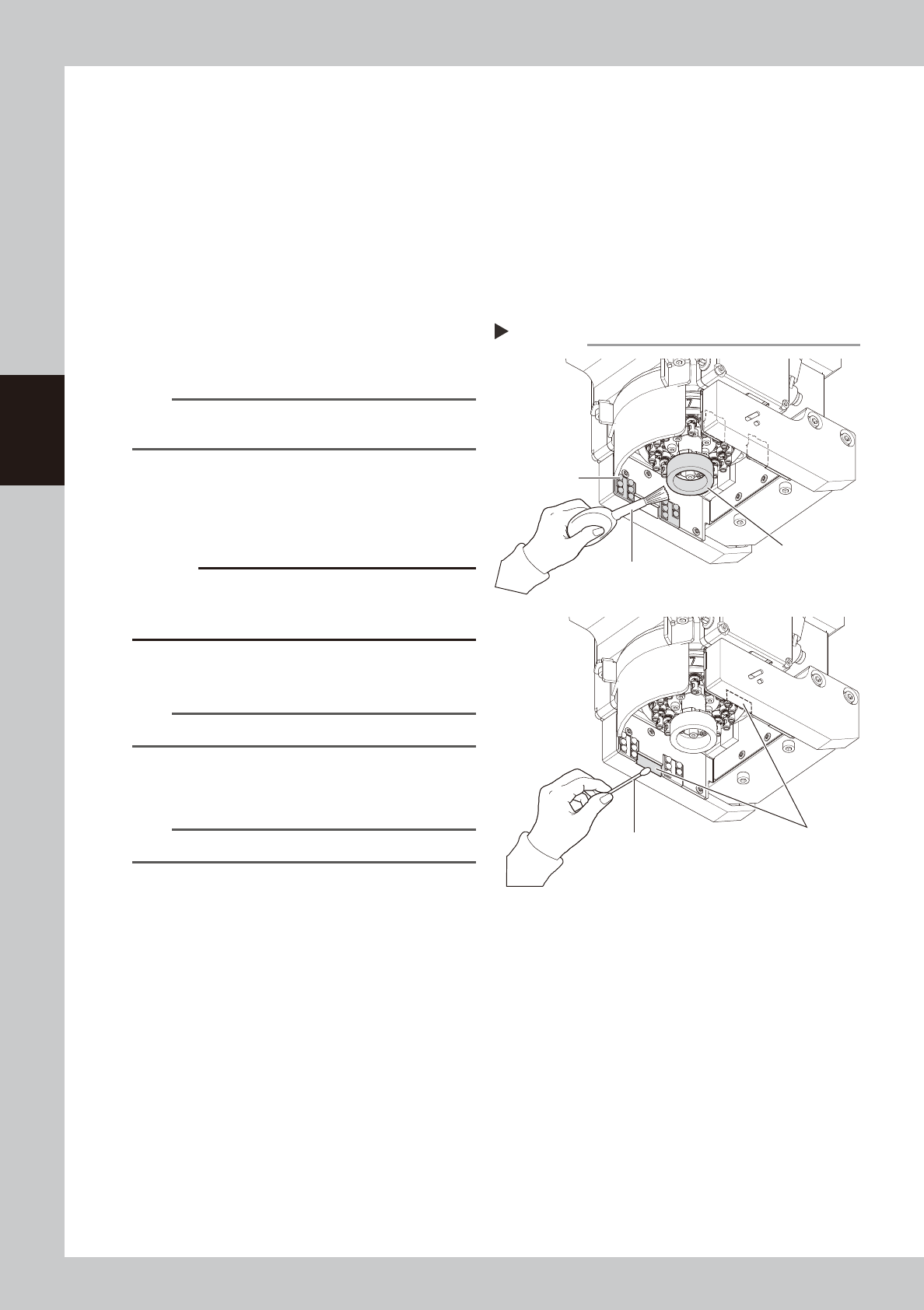
3
Clean the diffuser plate.
Use an optical brush to remove dust from
the diffuser plate and lighting surface.
53359-N9-10
c
CAUTION
When cleaning the diffuser plate, do not use a solvent
(including lens cleaner). Using a solvent may cause the
diffuser plate surface to discolor.
4
Clean the prisms.
Wipe the prisms with dry cotton swab.
TIP
Optical brush and lens cleaner are sold as options.
5
Return the nozzles.
Return each nozzle to the head.
n
NOTE
Return detached nozzle to the original head.
Cleaning RS head side-view lighting
Step 3-4
Diffuser plate
Lighting
(4 areas)
Cotton swab
Prism (2 areas)
Optical brush
3-53
3
Periodic maintenance items
5. 1-year maintenance
This section describes 1-year maintenance items.
5.1 MU head
5.1.1 Cleaning the spline shaft
Foreign matter and dust adhering to the inside of the spline shaft air path may cause pickup and placement
errors. To prevent this, the spine shaft interior should be cleaned once per year (general guideline), although
this may vary depending on the supplied air condition and the operating time.
c
CAUTION
If abnormal noise is emitted from a spline shaft or movement is unstable, contact YAMAHA sales representatives.
Disassembly and cleaning of the spline shaft by the user will void the warranty.
1
Prepare for work.
e
1. Remove all items sensitive to magnetic fields such as wristwatches and magnetic ID cards.
2. Return all nozzles to the nozzle station (when installed).
3. Press the emergency stop button to put the machine in emergency stop.
4. Use the CLAMP ON/OFF switch to lower the feeder exchange carriage and detach it.
5. Move the head unit to a position where easy to perform the task, and place a square cloth under
the head unit.
2
Detach the nozzles.
Detach all nozzles manually (when not
equipped with a nozzle station).
n
NOTE
After cleaning, each nozzle must be returned to the
head from which it was detached.
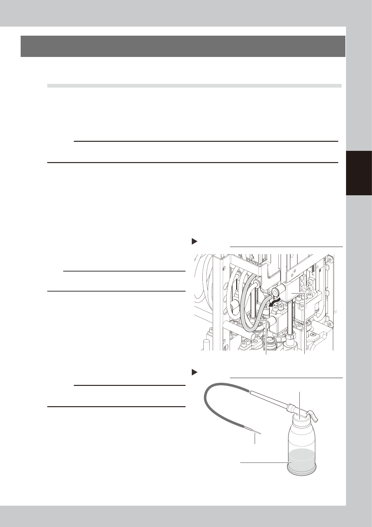
3
Disconnect the air hoses.
Disconnect all air hoses from the bearing
holders at each head.
53360-N9-00
4
Prepare the cleaning kit.
Pour IPA (isopropyl alcohol) into the
container of the cleaning kit (KHN-M8860-
00X).
53361-N9-00
c
CAUTION
Do not use any solvent other than IPA (isopropyl
alcohol).
Disconnecting the air hoses
Step 3
Air hose
Bearing holder
Cleaning kit
Step 4
Pump
Nozzle
IPA