YSM40R_Mainte_E.pdf - 第130页
3-60 3 Periodic maintenance items 5.3.2 Cleaning and greasing the hexagon spline T he cleaning and lubrication procedures for the conveyor's IN and OUT port hexagon splines are gi ven below . See "Chapter 5 Lub…
3-59
3
Periodic maintenance items
5
Remove the belt from the pulley.
Check that the removed belt is not cracked,
worn and frayed.
If the belt is cracked or worn, replace it
referring to "2.1 Replacing the conveyor
belt" in Chapter 6.
6
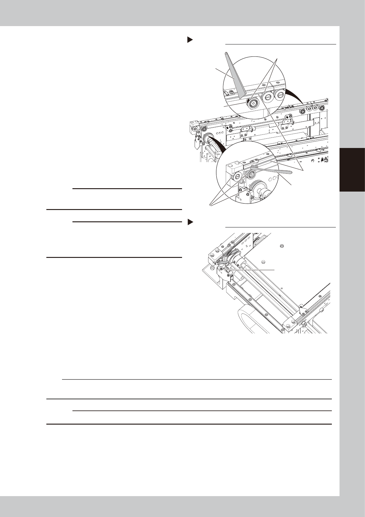
Clean the guides and pulleys.
1. Use a vacuum assembly (option) to
suction the belt wear debris on the belt
guides and sensors, etc.
2. Use a plastic spatula or similar tool to
remove the belt wear debris adhering to
the outer peripheral surface of the
pulleys.
3. Use a brush or similar tool to remove the
belt wear debris caught in the belt
guides.
53394-N9-00
c
CAUTION
Use a plastic spatula and brush to avoid scratching the
pulleys and guides.
c
CAUTION
Do not use a solvent (IPA, etc.) unless the guides and
pulleys are excessively dirty. If using a solvent, be
careful not to spill the solvent on the bearing in the
pulleys during cleaning.
7
Reattach the belt.
1. Temporarily place the belt on the belt
tensioner pulley.
2. Place the belt on the end pulley
removed in Step 4 and mount it with the
pulley shaft together with the washer.
3. Move the belt tensioner pulley to the
position marked in Step 4 and tighten the
bolt while applying tension.
4. If there is a slack in the belt, adjust the
position of the belt tensioner pulley to
apply proper tension.
53374-N9-00
n
NOTE
The specified conveyor belt tension for this machine is as follows. Use a tension gauge to adjust the belt tension as
needed. Stage 1 : 260 to 320Hz / Stage 2 : 180 to 220Hz
c
CAUTION
The tightening torque for the belt tensioner pulley is 5.5 N·m. Be careful not to overtighten.
8
Attach board clamp assembly.
1. Attach board clamp assembly to the original position. Mount it by tightening 4 bolts with hex wrench
(2.5).
2. Remove square cloth.
9
Return the tape cutter duct to the original position.
Tension measurement point
Step 7
Tension measurement point
(outer side of each lane)
Step 6
Spatula
(made of plastic)
Brush
Belt guides
Outer peripheral surface of pulley
Outer peripheral surface of pulley
Belt wear debris
sticking to pulley
Cleaning the guide and pulley
3-60
3
Periodic maintenance items
5.3.2 Cleaning and greasing the hexagon spline
The cleaning and lubrication procedures for the conveyor's IN and OUT port hexagon splines are given below.
See "Chapter 5 Lubricating points" for lubricating points and lubricating type.
1
Set the conveyor width to the
maximum.
Manually set the conveyor width to the
maximum.
2
Prepare for work.
e
1. Remove all items sensitive to magnetic
fields such as wristwatches and magnetic
ID cards.
2. Press the emergency stop button to put
the machine in emergency stop.
3. Use the CLAMP ON/OFF switch to lower
the feeder exchange carriage and
detach it.
3
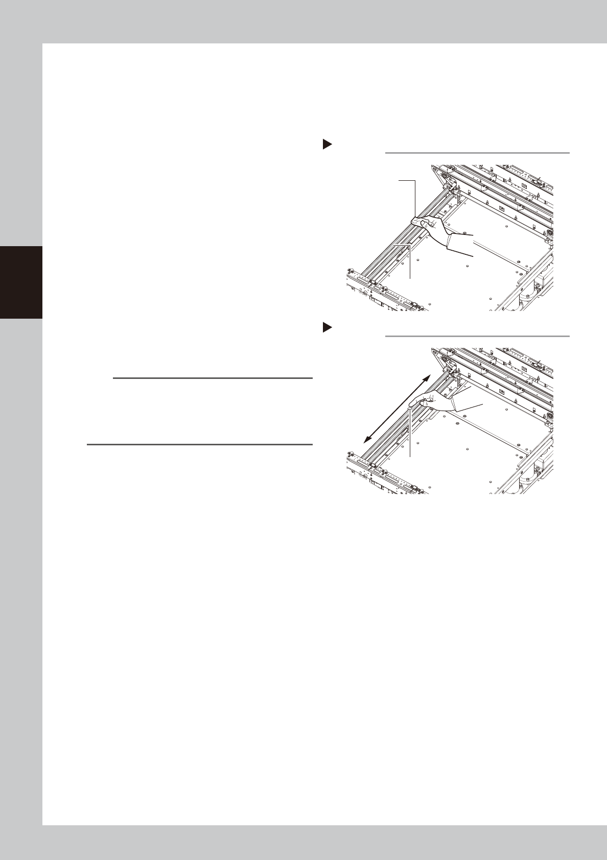
Clean the hexagon spline.
Wipe away old grease and dirt from the
entire hexagon spline with a lint-free cloth
(for clean room).
53376-N9-00
n
NOTE
If it is difficult to clean the hexagon spline due to the
tape cutter duct, then remove the tape cutter duct.
Note, however, that emergency stop cannot be
canceled when the tape cutter duct is removed. So
you will have to reattach it to cancel emergency stop.
4
Wipe the rest of the hexagon spline.
e
1. Set the feeder exchange carriage and
cancel emergency stop.
2. Narrow the conveyor width manually,
press the emergency stop button again,
and detach the feeder exchange
carriage.
3. Wipe the rest of the hexagon spline that
could not be wiped.
5
Apply grease.
Apply a uniform coat of the specified grease
(NSL) by hand over the surface of the
hexagon spline. As with Steps 3 to 4, adjust
the conveyor width to apply grease over the
entire hexagon spline.
53377-N9-00
Cleaning the hexagon spline
Step3
Cleaning cloth
Hexagon spline
Applying grease
Step 5
Apply a thin coat of
grease in a uniform
manner.
Grease
3-61
3
Periodic maintenance items
5.3.3 Cleaning/lubricating W-axis ball screw and guides
This section describes the procedure for cleaning and lubricating the conveyor W-axis ball screw and guides.
See "Chapter 5 Lubricating points" for lubricating points and lubricating type.
1
Set the conveyor width of Lane 1 to
the maximum.
Press the [Unit]-[Conveyor]-[Width] button
and set the conveyor width of Line 1 to the
maximum.
2
Lower the push-up plates of Lane 1.
Make sure that the push-up plates are
lowered. If not lowered, press the [Unit]-
[Conveyor]-[Push Up] button to lower the
push-up plates (2 plates for stages 1 and 2)
of Lane 1.
3
Prepare for work.
e
1. Remove all items sensitive to magnetic
fields such as wristwatches and magnetic
ID cards.
2. Press the emergency stop button to put
the machine in emergency stop.
3. Use the CLAMP ON/OFF switch to lower
the feeder exchange carriage and
detach it.
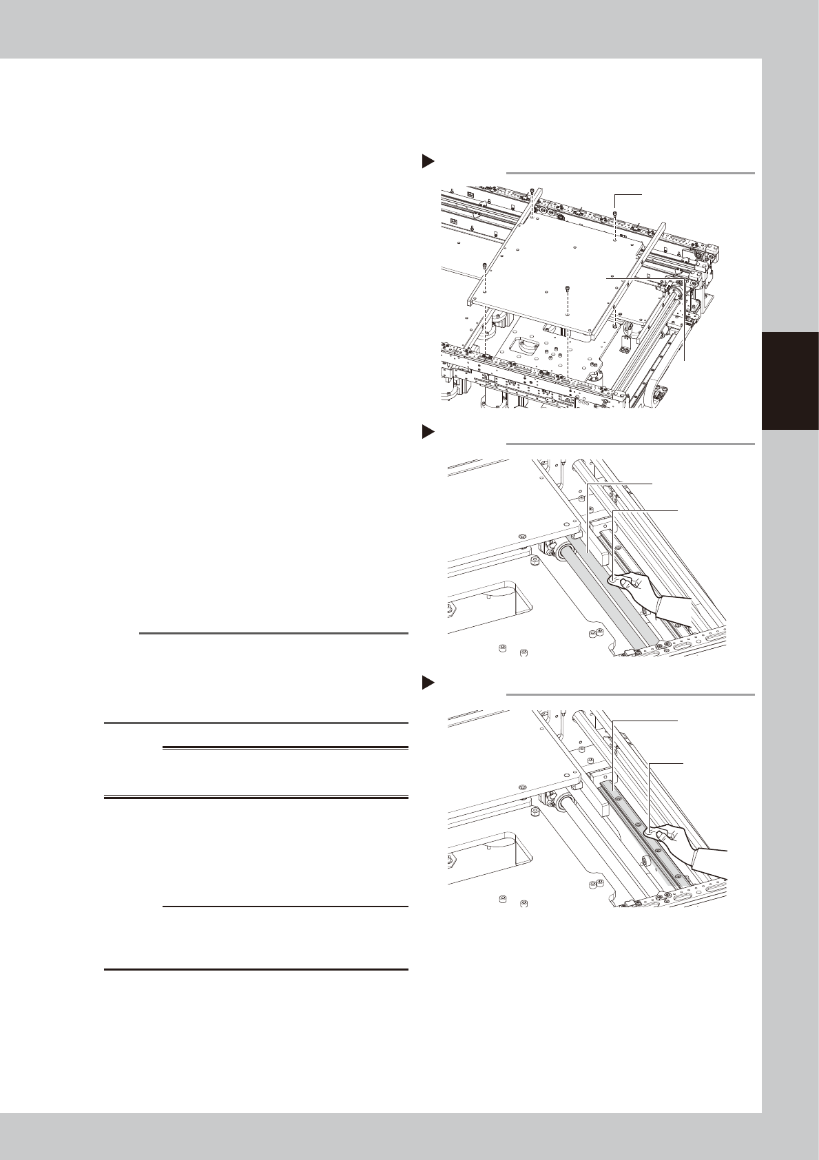
4
Detach the push-up plate.
Use a hex wrench (4) to remove the bolts (4
places per stage) that detach the push-up
plates, and then remove the push-up plates.
53378-N9-00
n
NOTE
If it is difficult to clean the ball screw and guide due to
the tape cutter duct, then remove the tape cutter
duct. Note, however, that emergency stop cannot be
canceled when the tape cutter duct is removed. So
you will have to reattach it to cancel emergency stop.
w
WARNING
THE PUSH-PLATE IS A HEAVY ITEM, AND IT MUST THEREFORE
BE HANDLED WITH CARE TO AVOID INJURY.
5
Clean the ball screw.
Wipe away old grease and dirt from the
entire ball screw with a lint-free cloth.
53379-N9-00
c
CAUTION
Carefully wipe the lead grooves of the ball screw during
cleaning. After cleaning, make sure that no dust, lint
and debris remain on the ball screw.
6
Clean the guide.
Wipe away old grease and dirt from the
entire guide with a lint-free cloth.
53380-N9-00
Removing the push-up plate
Step 4
Push-up plate securing
bolts (4 bolts)
Push-up plate
Cleaning the ball screw
Step 5
Cleaning cloth
Ball screw
Cleaning the guide
Step 6
Cleaning cloth
Guide