YSM40R_Mainte_E.pdf - 第142页
3-72 3 Periodic maintenance items 6.1.4 Replacing the blow valves T he blow valve (rod 1, rod 2 and blo w valve) of the air lines in RS head requires to replace every 2 y ears. 1 Pr epare for work. e 1. Remove all items …
3-71
3
Periodic maintenance items
4
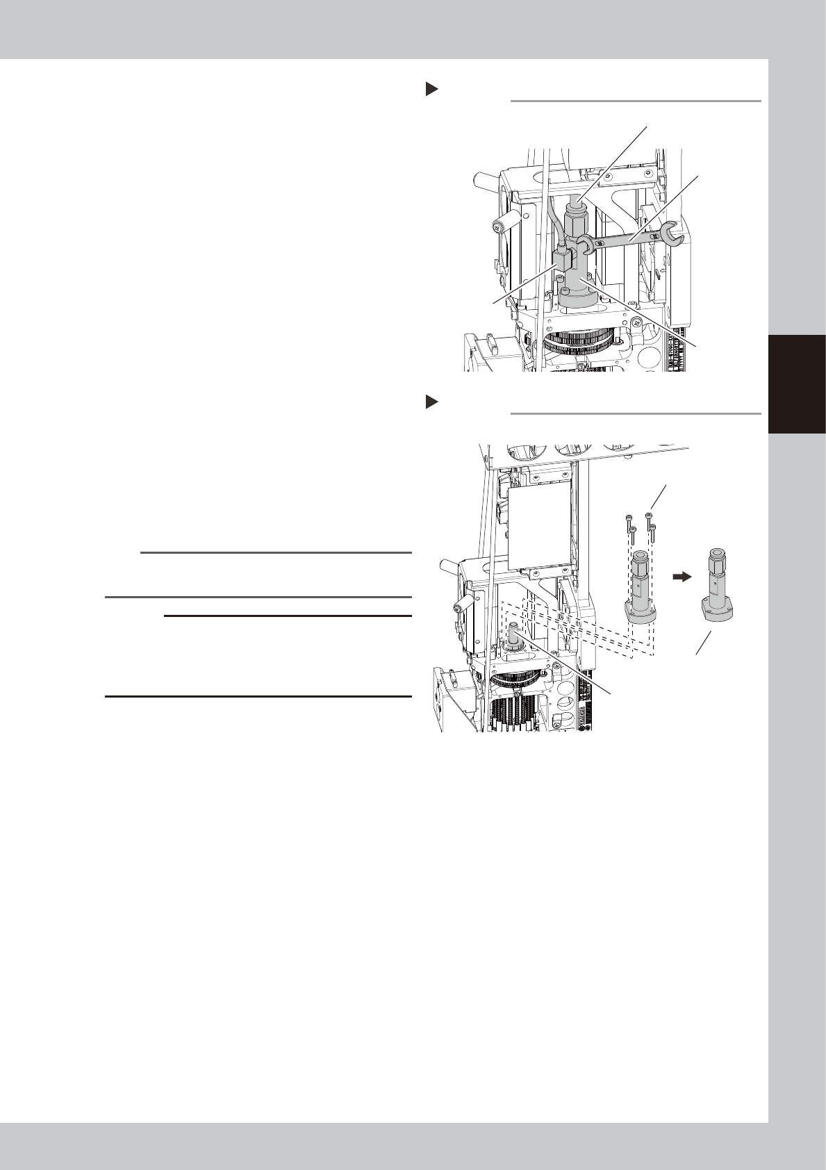
Detach the vacuum sensor.
1. Disconnect the vacuum line hose.
2. Use a wrench (7) to detach the vacuum
sensor connected to the Packing
Assembly.
53397-N9-00
5
Detach the Packing assembly.
1. Use a hex wrench (2.5) to remove the
bolts that mount the Packing assembly.
2. Detach the Packing assembly by pulling
it upward.
3. Wipe away old grease from the shaft on
the head side with a lint-free cloth.
53398-N9-00
6
Replace the Packing assembly.
1. Insert a new Packing Assembly onto the
shaft.
2. Tighten the bolts to mount the Packing
Assembly.
3. Insert the vacuum line hose into the
fitting.
4. Reattach the vacuum sensor to the
Packing Assembly.
n
NOTE
The Packing assembly contains grease-coated
packings.
c
CAUTION
When attaching the vacuum sensor, make sure the
sensor mount faces straight the Packing assembly. If
slanted, tightening the sensor mounting nut may
damage the parts.
7
Reattach the head cover.
8
Return Z-axis unit to original
position.
1. Return Z-axis unit to the original position
and connect the connector.
2. Remove square cloth.
Detaching vacuum sensor
Step 4
Wrench (7)
Vacuum line hose
Vacuum sensor
Packing
assembly
Detaching packing assembly
Step 5
Shaft
Packing assembly bolts
Packing assembly
3-72
3
Periodic maintenance items
6.1.4 Replacing the blow valves
The blow valve (rod 1, rod 2 and blow valve) of the air lines in RS head requires to replace every 2 years.
1
Prepare for work.
e
1. Remove all items sensitive to magnetic
fields such as wristwatches and magnetic
ID cards.
2. Press the emergency stop button and
then open the machine safety cover.
3. Use the CLAMP ON/OFF switch to lower
the feeder exchange carriage and
detach it.
4. Move the head unit to a convenient
position for maintenance work. Place a
square cloth under it.
5. Power off the machine.
6. Shut off the air supply to the machine.
2
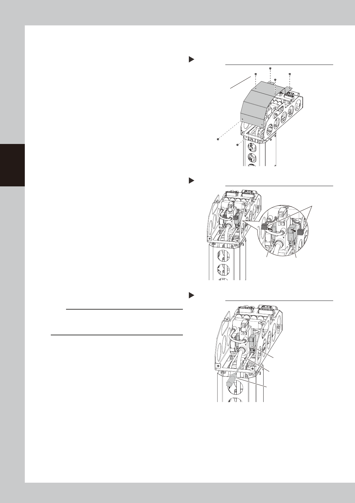
Detach the cover of the upper part
of the RS head.
Detach the cover mounting screws of the
upper part of the RS head with a Phillips
screwdriver.
533D7-N9-00
3
Disconnect blow valve connector.
533D8-N9-00
4
Replace the valve.
1. Detach the valve mounting screws with a
Phillips precision screwdriver.
2. Replace the valve with the new one.
3. Return the connector to the original
position.
533D9-N9-00
n
NOTE
The packing is attached to the back of the valve.
Replace the valve with a new one while carefully
checking the packing for dropping or catching.
5
Return head upper cover to original
position.
Detaching the cover
Step 2
Cover mounting screws
Disconnecting the valve conector
Step 3
Conector
Blow valve for rod 2 Blow valve for rod 1
Replacing the blow valve
Step 4
Phillips precision screwdriver
The packing is attached to
the back of the valve.
Carefully check this packing.
Valve mounting screw
3-73
3
Periodic maintenance items
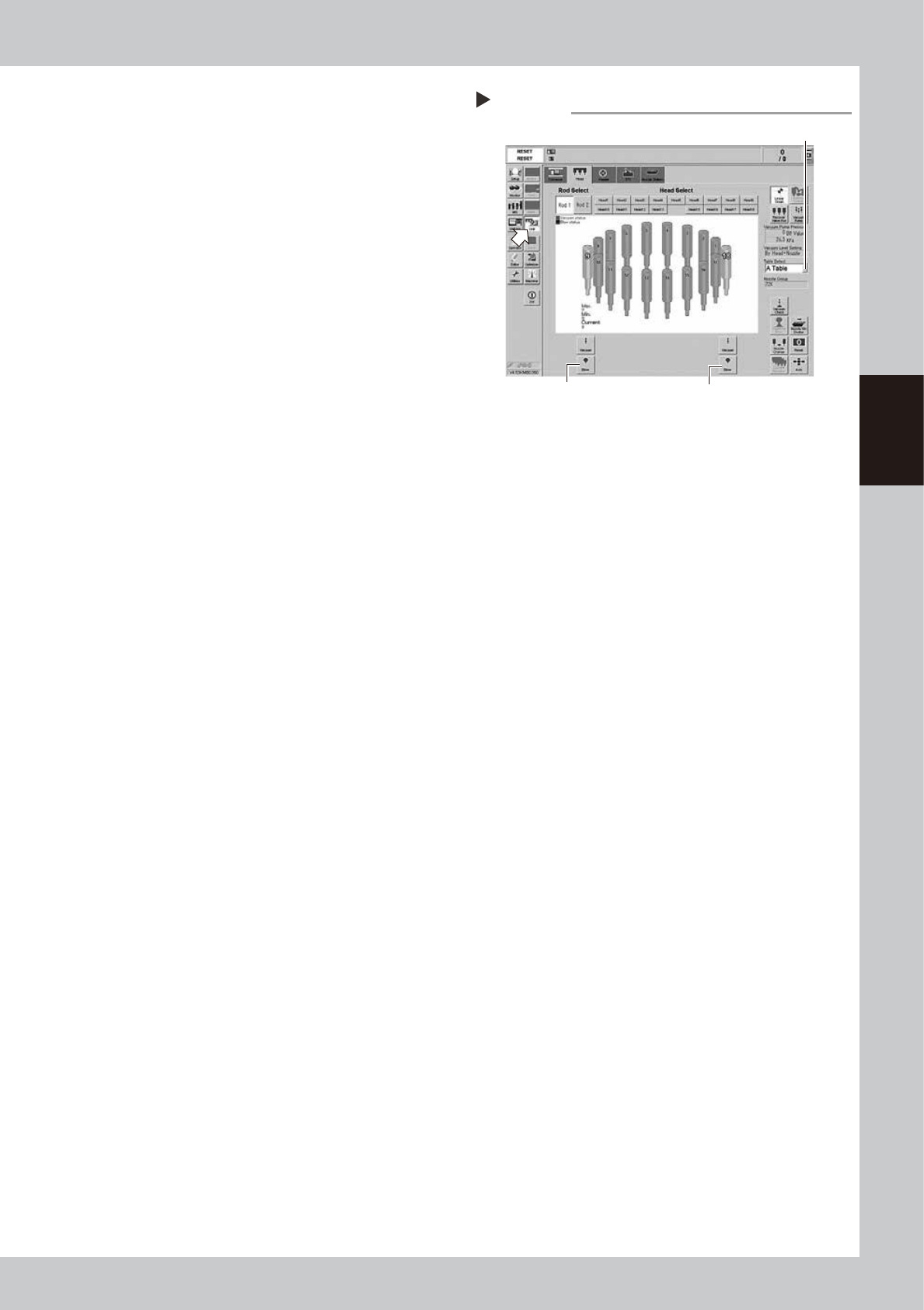
6
Check the valve operation.
1. Turn on the air supply and main power
supply. Then launch the application.
2. Open the [Unit]-[Head] tab.
3. Press the [Table select] button and select
the table (head unit) that the valve was
replaced.
4. The [Blow] buttons locate on the bottom
of the screen. Press the [Blow] button
that the rod was replaced (Rod 1: left
side, Rod 2: Right side of the screen).
e
5. Press the emergency stop button. Open
the machine cover and check that the
blow air is property flowing out from the
tip of the head.
54300-N9-00
RS head blow check
Step 6
Table select button
Rod1 [Blow] button Rod2 [Blow] button