YSM40R_Mainte_E.pdf - 第156页
3-86 3 Periodic maintenance items 5 Pr eclean inside of shaft with brush. Preclean inside of nozzle shaft with brush to remove dirt or foreign objects easily. 1. Insert spline brush (KMB-M3858-00X) deeply into the nozzle…
3-85
3
Periodic maintenance items
8. Others
8.1 Cleaning inside of nozzle shaft on RS head unit
When the vacuum level does not go down to 100 or less while nozzle is detached from RS head unit, replace with new
filter as a general. If vacuum level does not go down to the standard value even after replacing filter, The air path in
spline shaft may be dirty. In this case, it is required to clean the inside of nozzle shaft.
Note that clean 18 shafts of all heads as a rule even the vacuum level of one head does not go down to the standard
value as shaft inside of other heads may be dirty.
1
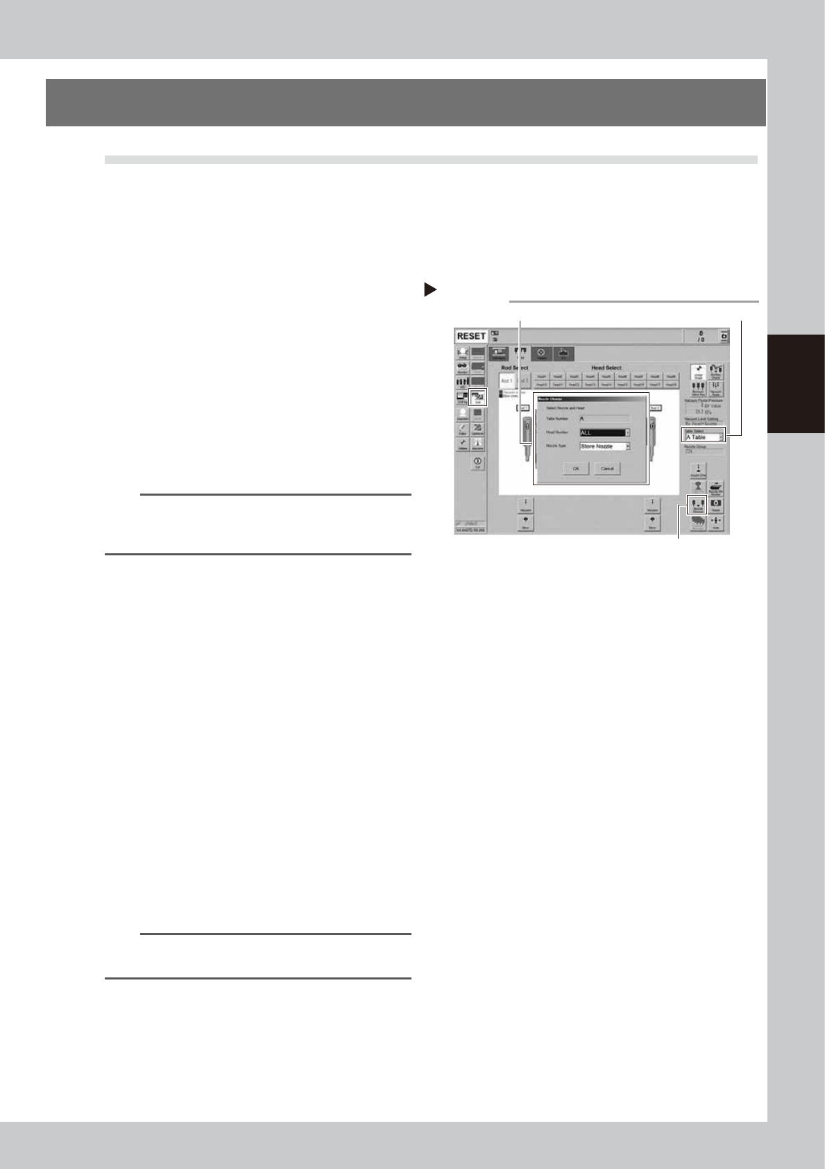
Store all nozzles to nozzle station.
1. Open the [Unit] - [Head] screen.
2. Select desired head unit from "Table
Select".
3. Press the [Nozzle Change] button.
4. Select "ALL" for "Head Number" and
select "Store Nozzle" for "Nozzle Type" on
the "Nozzle Change" screen.
5. Press the [OK] button to return all nozzles
to the nozzle station.
54305-N9-00
n
NOTE
If the machine is not equipped with a nozzle station,
press the emergency stop button and then detach the
nozzles manually.
2
Prepare for work.
e
1. Remove all items sensitive to magnetic
fields such as wristwatches and magnetic
ID cards.
2. Press the emergency stop button and
then open the machine safety cover.
3. Use the CLAMP ON/OFF switch to lower
the feeder exchange carriage and
detach it.
4. Move the head unit to convenient
position to work and place a square
cloth under the head unit.
3
Detach all filters.
See Step 3 in "2.6.1 Inspecting and replacing
the air filters" to detach all filters.
4
Clean and lubricate all spools.
See "3.2.3 Cleaning and lubricating the
vacuum selector (spool)" to clean and
lubricate all spools.
TIP
It is not necessary to return detached spools to the
original positions.
Step 1
Storing nozzles
Head Number: “ALL” / Nozzle type: “Store Nozzle”
[Nozzle Change] button
Table Select
3-86
3
Periodic maintenance items
5
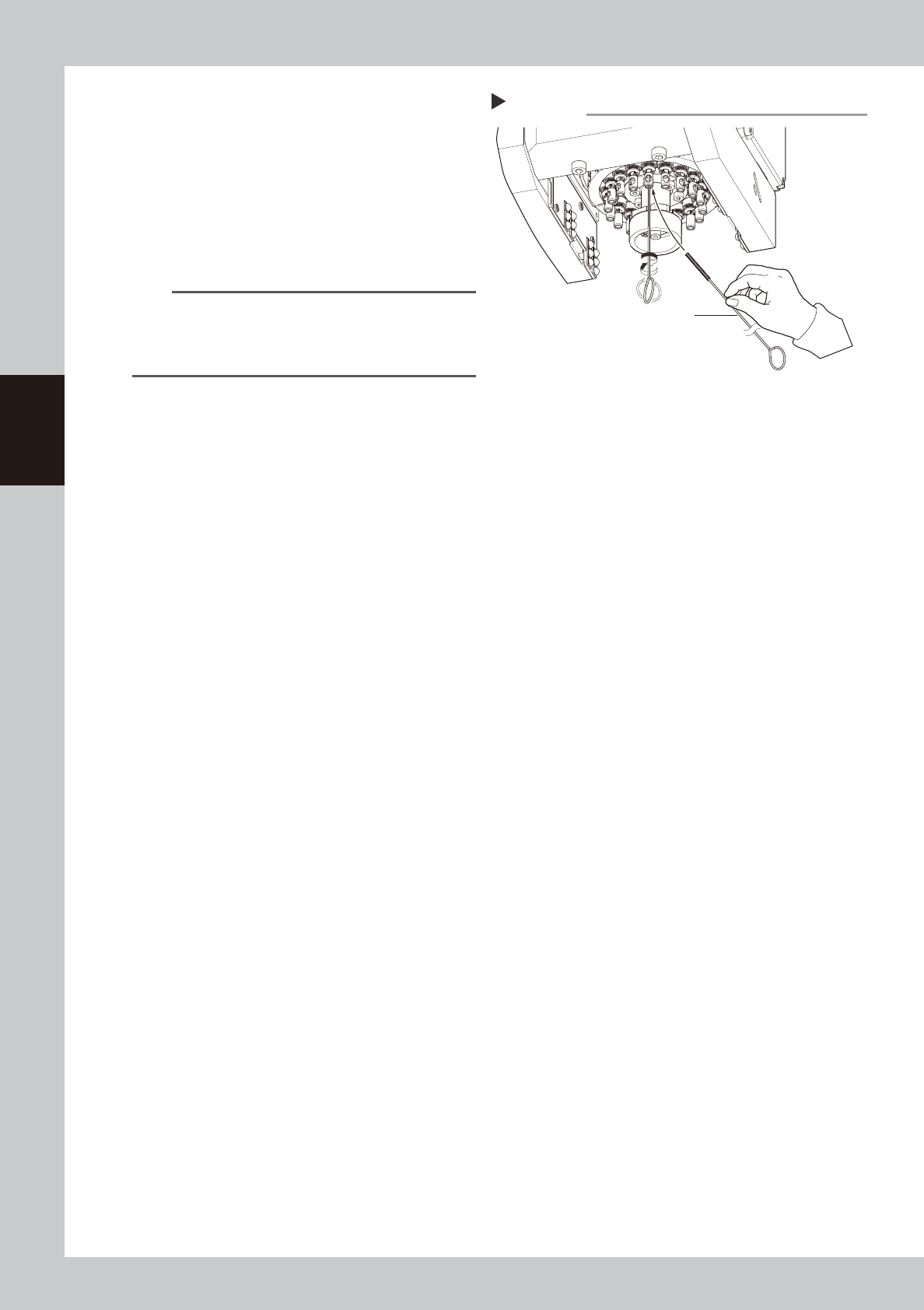
Preclean inside of shaft with brush.
Preclean inside of nozzle shaft with brush to
remove dirt or foreign objects easily.
1. Insert spline brush (KMB-M3858-00X)
deeply into the nozzle shaft.
2. Turn it left/right several times.
3. Clean the rest of spline shaft insides with
the same procedures above.
533F6-N9-00
n
NOTE
• Do not hold edge of spline brush. Doing so may
bend the brush.
• A spline brush can clean all 18 heads of RS head
unit, although this may vary depending on dirt.
Precleaning inside of shaft
Step 5
Spline brush
3-87
3
Periodic maintenance items
6
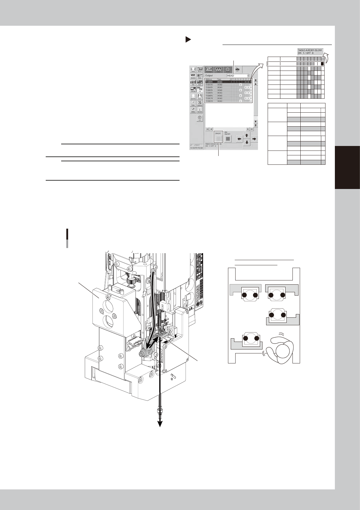
Turn on the blow.
1. See " Blow air path on RS head unit"
below for checking head unit/rod
number to blow.
2. Switch to [Unit] - [I/O] screen. Select
"HEAD" for "Output".
3. Click "Rod 1 (or 2)" that is checked on 1
and to be used. Then press [ON]/[OFF]
button to open blow valve for relevant
rod ("0
→
1").
4. Open blow valve for relevant unit with
same procedures above ("0
→
1").
54306-N9-00
n
NOTE
Open the valve for either "Rod 1" or "Rod 2".
TIP
The blow air is supplied from shaft tip on bottom of rod
by opening both "Rod 1 (or 2)" and "Blow switch" valves.
n
Blow air path on RS head unit
Seen RS head unit from front, the air hose on the right is called "Rod 1 air line". The other side is called "Rod 2 air line".
When using blow air for RS head maintenance, select a rod based on checking the head unit to be maintained, worker's
position, and rod position.
Positions of head unit and rod
Rod 2 side
Rod 1 air line
1
2
21
21
1
2
A
B
C
D
When maintaining head unit C,
blow it from rod 2 side.
533G3-N9-00
Turning on blow
Step 6
Select head
T130070 HEAD
Address Type 7 6 5 4 3 2 1 0
T130470 HEAD
T130570 HEAD
T130870 HEAD
T130970 HEAD
T130C70 HEAD
T130D70 HEAD
T130170 HEAD
1 0
0 0
0 0 0
0 0
1 0 0
0 0
0 0 0
0 0
Head unit
A (Table A)
Blow switch
ROD
1
ROD 2
T130070 1
T130070 0
T130170 0
B (Table B)
Blow switch
ROD
1
ROD 2
T130470 1
T130470 0
T130570 0
C (Table C)
Blow switch
ROD
1
ROD 2
T130870 1
T130870 0
T130970 0
D (Table D)
Blow switch
ROD
1
ROD 2
T130C70 1
T130C70 0
T130D70 0
0
[ON/OFF] button
AddressValve