YSM40R_Mainte_E.pdf - 第157页
3-87 3 Periodic maintenance items 6 T urn on the blow . 1. See " Blow air path on RS head unit" below for checking head unit/rod number to blow. 2. Switch to [Unit] - [I/O] screen. Select "HEAD" for &…
3-86
3
Periodic maintenance items
5
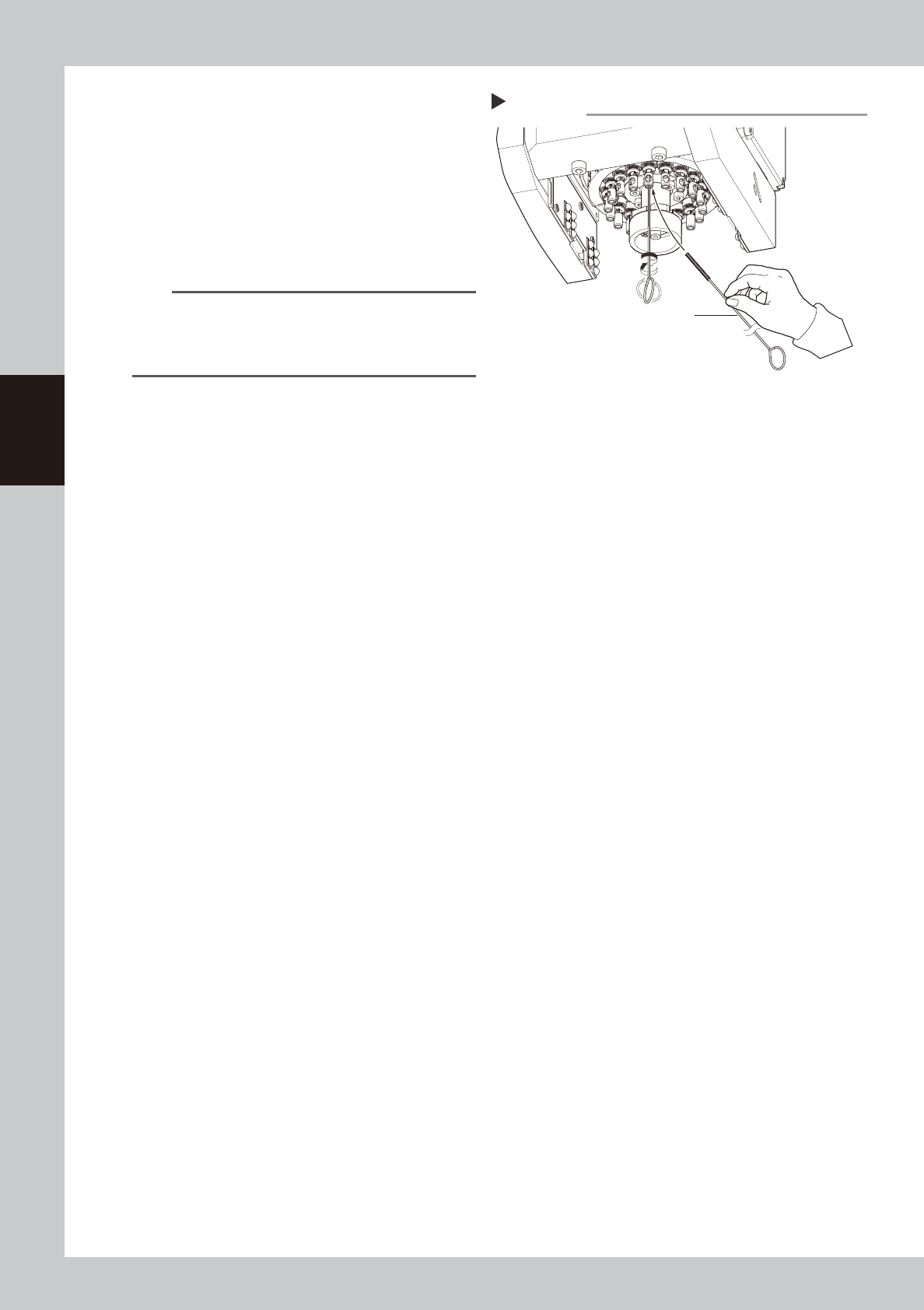
Preclean inside of shaft with brush.
Preclean inside of nozzle shaft with brush to
remove dirt or foreign objects easily.
1. Insert spline brush (KMB-M3858-00X)
deeply into the nozzle shaft.
2. Turn it left/right several times.
3. Clean the rest of spline shaft insides with
the same procedures above.
533F6-N9-00
n
NOTE
• Do not hold edge of spline brush. Doing so may
bend the brush.
• A spline brush can clean all 18 heads of RS head
unit, although this may vary depending on dirt.
Precleaning inside of shaft
Step 5
Spline brush
3-87
3
Periodic maintenance items
6
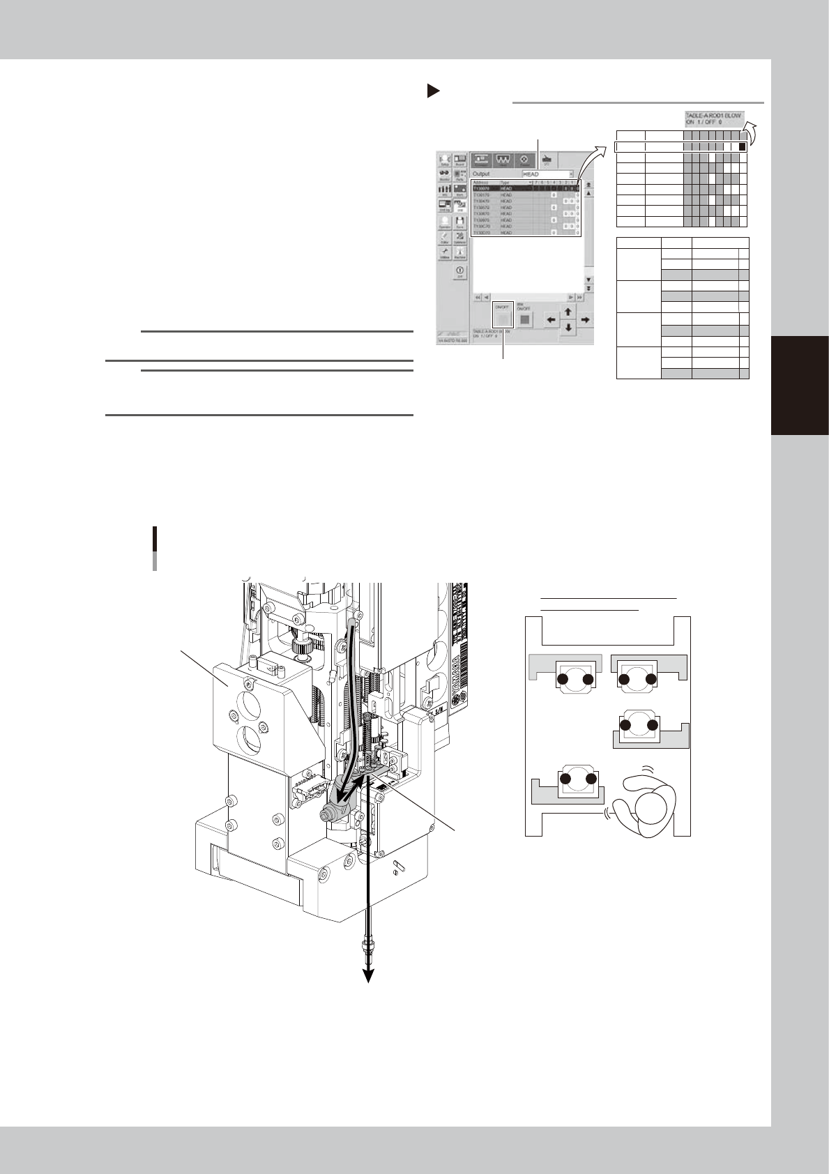
Turn on the blow.
1. See " Blow air path on RS head unit"
below for checking head unit/rod
number to blow.
2. Switch to [Unit] - [I/O] screen. Select
"HEAD" for "Output".
3. Click "Rod 1 (or 2)" that is checked on 1
and to be used. Then press [ON]/[OFF]
button to open blow valve for relevant
rod ("0
→
1").
4. Open blow valve for relevant unit with
same procedures above ("0
→
1").
54306-N9-00
n
NOTE
Open the valve for either "Rod 1" or "Rod 2".
TIP
The blow air is supplied from shaft tip on bottom of rod
by opening both "Rod 1 (or 2)" and "Blow switch" valves.
n
Blow air path on RS head unit
Seen RS head unit from front, the air hose on the right is called "Rod 1 air line". The other side is called "Rod 2 air line".
When using blow air for RS head maintenance, select a rod based on checking the head unit to be maintained, worker's
position, and rod position.
Positions of head unit and rod
Rod 2 side
Rod 1 air line
1
2
21
21
1
2
A
B
C
D
When maintaining head unit C,
blow it from rod 2 side.
533G3-N9-00
Turning on blow
Step 6
Select head
T130070 HEAD
Address Type 7 6 5 4 3 2 1 0
T130470 HEAD
T130570 HEAD
T130870 HEAD
T130970 HEAD
T130C70 HEAD
T130D70 HEAD
T130170 HEAD
1 0
0 0
0 0 0
0 0
1 0 0
0 0
0 0 0
0 0
Head unit
A (Table A)
Blow switch
ROD
1
ROD 2
T130070 1
T130070 0
T130170 0
B (Table B)
Blow switch
ROD
1
ROD 2
T130470 1
T130470 0
T130570 0
C (Table C)
Blow switch
ROD
1
ROD 2
T130870 1
T130870 0
T130970 0
D (Table D)
Blow switch
ROD
1
ROD 2
T130C70 1
T130C70 0
T130D70 0
0
[ON/OFF] button
AddressValve
3-88
3
Periodic maintenance items
7
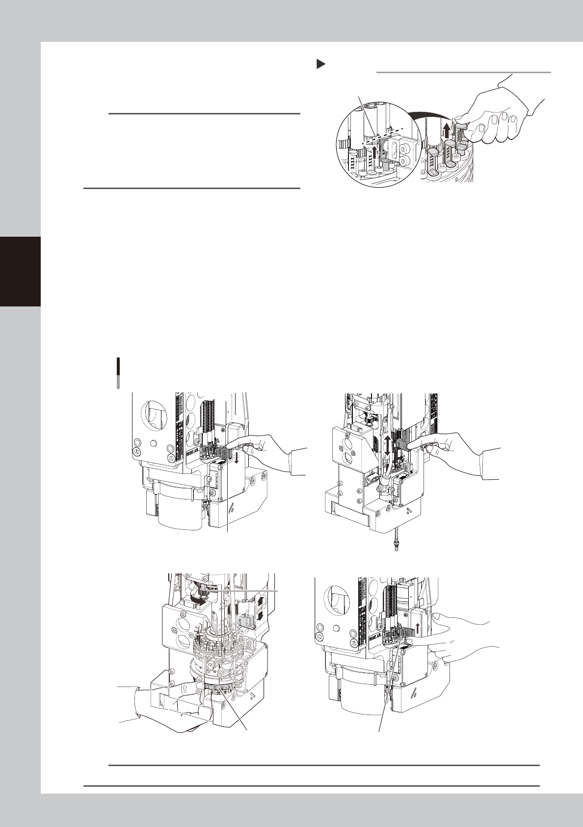
Set all spools to "Vacuum position".
Move all spools on relevant head unit to
upper end (vacuum position).
533G4-N9-00
TIP
The spool upper end locates where it can be moved
up without resistance. The spool can be moved up to
the middle of gear on shaft (upper gear). The stroke of
top/bottom of spool is approx. 3 mm. The spool is
detached by moving it up more than 3 mm. Make sure
not to move it up excessively.
8
Blow the inside of shaft.
1. Pressing down V-axis of relevant rod side manually lowers the relevant spool and blows the inside of
nozzle shaft.
2. Move up/down Z-axis knob on relevant rod side several times to move up/down shaft under the
knob.
3. R (mount angle) of all heads can be turned not by turning rotary but by turning R-axis gear holding
the label where head numbers are indicated with hand. Turn them 120 degrees.
4. Move up/down Z-axis knob of relevant rod several times to move up/down shaft under Z-axis.
5. Perform the works from 3 to 4 again.
6. Move up V-axis manually to move the relevant spool to the upper end (vacuum position).
7. Turn the rotary to perform the works from 1 to 6 for all heads.
Blowing the inside of shaft
Moving down V-axis: Blow
Moving up V-axis: Vacuum (stop blowing)
R-axis gear
Hold here with hand. Moving up V-axis: Vacuum (stop blowing)
1
8- 28-
3
8- 68-
533G5-N9-00
n
NOTE
It requires approx. 30 seconds to blow per head. If dirt cannot be removed, blow a little longer.
Moving up spool
Step 7
Spool upper end: meddle of shaft gear (upper side)