YSM40R_Mainte_E.pdf - 第194页
6-4 6 How to replace consumable parts 1.3 Replacing the roller lock (FL head) e 1 Detach the nozzle. 1. Press the emergency stop button and then open the machine safety cover . 2. T ur n off the carriage clamp switch to …
6-3
6
How to replace consumable parts
1.2 Replacing nozzle leaf springs (FL head)
e
1
Detach the nozzle.
1. Press the emergency stop button and
then open the machine safety cover.
2. Turn off the carriage clamp switch to
detach carriage from mounter.
3. Detach relevant nozzle with leaf springs
manually.
c
CAUTION
When the machine is equipped with a nozzle station,
return all nozzles to the nozzle station.
2
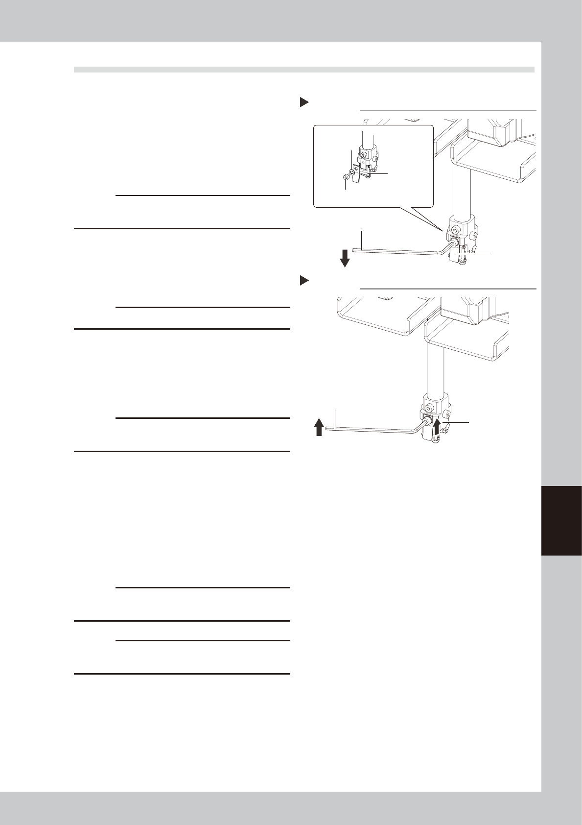
Detach the leaf springs.
Use a hex wrench (1.5) to remove the
mounting bolt and detach the lead spring.
53602-N9-00
c
CAUTION
Only remove the bolt of leaf springs.
3
Install the new leaf spring.
Tighten the mounting bolt with a hex wrench
(1.5) while pushing the leaf springs against
the upper portion.
53603-N9-00
c
CAUTION
Always attach the leaf springs so that they become
parallel.
4
Reattach the nozzle.
5
Check that the nozzle is held
securely.
1. Check that there is no gap between the
leaf springs and the nozzle arm assembly.
2. Attempt detaching and attaching the
nozzle several times to check that there
is no looseness.
c
CAUTION
When the machine is equipped with a nozzle station,
return all nozzles to the nozzle station.
c
CAUTION
Return each nozzle to the head from which it was
detached.
Detaching the leaf spring
Step 2
Hex wrench
Leaf spring
Leaf spring mounting bolt
Washer
Nozzle arm
assembly
Installing the leaf spring
Step 3
Hex wrench
Push the leaf
spring upward.
6-4
6
How to replace consumable parts
1.3 Replacing the roller lock (FL head)
e
1
Detach the nozzle.
1. Press the emergency stop button and
then open the machine safety cover.
2. Turn off the carriage clamp switch to
detach carriage from mounter.
3. Detach relevant nozzle with leaf springs
manually.
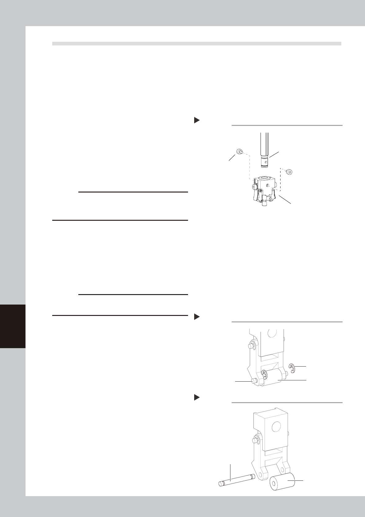
2
Replace the nozzle arm assembly.
1. Use a hex wrench (1.5) to remove the
bolt that mounts the nozzle arm
assembly.
2. Detach the nozzle arm assembly by
pulling it downward.
3. Attach a new nozzle arm assembly to the
nozzle shaft.
c
CAUTION
The O-ring is used for the shaft. So, be careful not to
damage the O-ring when pulling out the nozzle arm
assembly.
53604-N9-00
3
Check the attached condition.
1. Check that there is no gap between the
leaf springs and roller.
2. Attempt detaching and attaching the
nozzle several times to check that there
is no looseness.
c
CAUTION
Return each nozzle to the head from which it was
detached.
n
Replacing only the roller
The following describes how to replace only the roller
after the nozzle arm assembly has been detached.
1
Detach the circlip.
Push the circlip of the roller shaft with a
precision slotted screwdriver to detach it.
53605-N9-00
2
Detach the roller.
Pull out the shaft and detach the roller.
3
Attach new roller.
Insert shaft into new roller and nozzle arm
assembly.
53606-N9-00
4
Attach the circlip.
Attach the circlip with a slotted precision
screwdriver.
Detaching nozzle arm assembly
Step 2
Nozzle arm assembly
Nozzle arm assembly
mounting bolt
O-ring
Detaching the circlip
Step 1
Shaft
Circlip
Roller
Attaching a new roller
Step 3
Shaft
New roller
6-5
6
How to replace consumable parts
2. Replacing conveyor belt
The conveyor belt should be replaced if excessive slack, grime or fraying is found after checking it as
described in "5.3.1 Inspecting conveyor belt and cleaning guide and pulley" in Chapter 3. Use the
following procedure to replace the belt.
2.1 Replacing the conveyor belt
1
Prepare for work.
e
1. Remove all items sensitive to magnetic
fields such as wristwatches and magnetic
ID cards.
2. Press the emergency stop button and
then open the machine safety cover.
3. Use the CLAMP ON/OFF switch to lower
the feeder exchange carriage and
detach it.
4. Detach the tape cutter duct.
5. Place a square cloth on the push-up
plate.
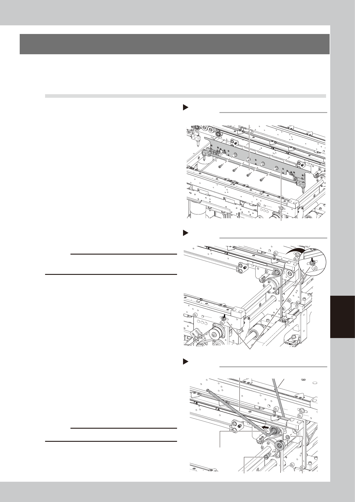
2
Detach the board clamp assembly.
Use a hex wrench (2.5) to remove the bolts (4
places shown in the figure at right) that
mount the board clamp assembly.
53607-N9-00
c
CAUTION
Do not remove any bolts other than the 4 bolts shown in
the figure at right.
3
Put a mark at the pulley position.
Using an oil-based pen, put a mark to
indicate the position of the bolt that mounts
the tensioner pulley.
53608-N9-00
4
Loosen the belt.
1. Use two hex wrenches to loosen the belt
tensioner pulley and move it to the end
of the tension adjusting slot (in the
loosening direction).
Hex wrench on pulley side : 5 mm
Hex wrench on bolt side : 4 mm
2. Use a slotted screwdriver to detach the
end pulley shaft next to the tensioner
pulley just loosened and then detach the
end pulley.
53609-N9-00
c
CAUTION
Use care to avoid losing the washers.
Detaching board clamp assembly
Step 2
Board clamp assembly
Board clamp assembly mounting bolts
Loosening the belt
Step 4
Hex wrench (5)
Hex wrench (4)
Loosen this pulley.
WasherRemove this pulley.End pulley shaft
Marking the pulley position
Step3
Use an oil-based pen to mark the pulley position.