YSM40R_Mainte_E.pdf - 第205页
A-5 Appendix 2. Maintenance par ts 2.1 YSM40R main unit maintenance par ts list c CAUTION The parts (part Nos.) in this manual were described at the time of manual issue. The part Nos. are subject to change without notic…
A-4
Appendix
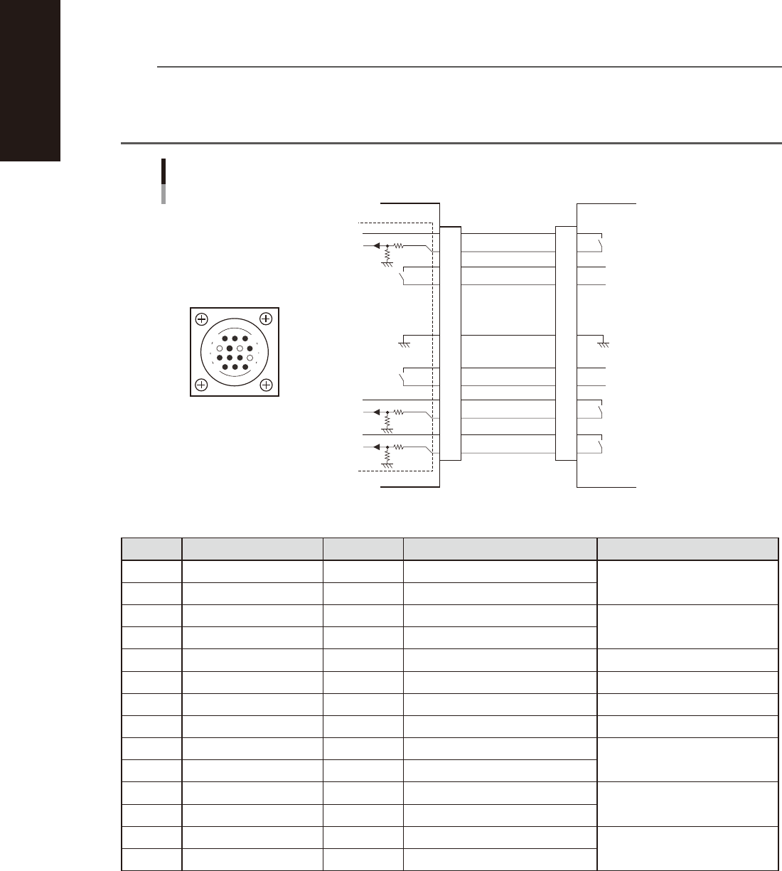
1.3.2 NEXT INTERFACE connector
When the following three conditions are met, the NEXT INTERFACE circuit in the machine allows the board to
be carried out.
1. Machine is ready for carrying out the board (BA OUT: ON)
2. Board carry-in signal is input from the downstream machine. (BUSY IN [N0100420] : ON)
3. Automatic operation signal is input from the downstream machine. (LR IN [N0100423] : ON)
n
NOTE
• When the automatic operation signal (LR IN) from the downstream machine turns off during transfer of a board,
the machine stops temporarily carrying out the PC.
• When the board being carried out is detected by the exit sensor, the BA OUT signal turns off.
• Carrying out the board is finished when both the BUSY IN and BA OUT turn off.
1
2
3
4
5
6
7
8
9
10
11
12
13
14
BUSY IN
(N0100420)
+24V
+24V
UR OUT(T01000E6)
LR IN
(N0100423)
+24V
LE IN
(N0100424)
BA OUT
(T01000E5)
Signal output during waiting
for board between machines
I/O BOARD
GND GND
14
11
12
7
4
8
3
1
Signal output during board
carry-in
Signal input to request board
carry-out
NEXT INTERFACE circuit
NEXT INTERFACE
connector
NEXT INTERFACE
AMP 206043-1
(14-pin receptacle)
This machine
Downstream machine
Signal input during automatic
operation
Signal output during automatic
operation
53A05-N9-00
n
Board transfer signal specifications (NEXT INTERFACE)
Pin No. Signal name Address I/O specifications Signal specifications
1 +24V Input common (+24V)
Signal input during board carry-in
2 BUSY IN N0100420 Voltage input
3 BA OUT T01000E5 Relay contact (zero voltage) output
Signal output to request board
carry-out
4 BA OUT T01000E5 Relay contact (zero voltage) output
5 NC
6 NC (with dummy pins) (Prevents misinsertion.)
7 GND
8 NC
9 UR OUT T01000E6 Relay contact (zero voltage) output
Signal output during automatic
operation
10 UR OUT T01000E6 Relay contact (zero voltage) output
11 +24V Input common (+24V)
Signal input during automatic
operation
12 LR IN N0100423 Voltage input
13 +24V Input common (+24V)
Signal input during waiting for
board between machines
14 LE IN N0100424 Voltage input
A-5
Appendix
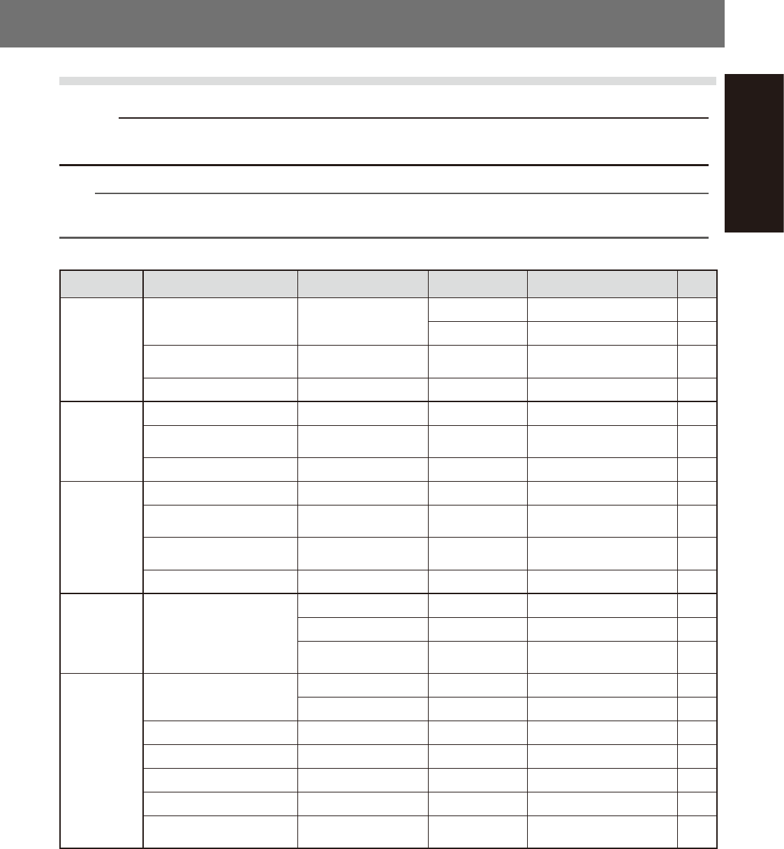
2. Maintenance parts
2.1 YSM40R main unit maintenance parts list
c
CAUTION
The parts (part Nos.) in this manual were described at the time of manual issue. The part Nos. are subject to change
without notice. Make sure to obtain the latest information on part names and part Nos. when purchasing.
n
NOTE
• The consumable part positions and the replacement procedure are described in this manual.
• See "2.1 Consumable parts" in Chapter 1 for nozzle consumable parts.
n
Consumable parts list
Position Name Part Name Part No. Note Qty
RS head unit
Air filter FILTER
KMB-M7070-00X 1 pc 18
*1
KMB-M3857-01X 1000 pcs per set -
*1
Packing assembly PACKING ASSY KMB-M70SP-00X
RS head vacuum line
replacement part
1
*1
Blow valve for ROD1/2 VALVE KMB-M7055-00X 2
*1
MU head unit
Nozzle leaf spring LEAF SPRING KG7-M7137-A0X 20
*1
Nozzle leaf spring mounting
screw
SCREW,PAN HEAD 90990-08J016 M2 x L2.5 20
*1
Air filter FILTER KLF-M7156-00X 10
*1
FL head unit
Nozzle leaf spring PLATE, SPRING KV7-M8171-00X 4
*1
Nozzle leaf spring mounting
screw
BOLT HEX,
SOCKETHEAD
90115-02J004 4
*1
Nozzle leaf spring mounting
washer
WASHER, PLAIN 90990-28J002 4
*1
Air filter FILTER KLF-M7156-00X 2
*1
Conveyor belt
Conveyor belt
BELT, CONVEYOR 1 KLF-M9110-00X [Lane 1] Length: 1180 mm 4
*2
BELT, CONVEYOR 2 KLF-M9117-00X [Lane 1] Length: 1256 mm 4
*2
BELT, CV1 KLF-M9177-01X
For extension conveyor
Length: 1524 mm
4
*3
Base
Controller filter
MEDIA FILTER KLA-M53A9-00X For system controller 1
FILTER KLA-M53A8-00X For servo controller 1
Ceiling fan filter FILTER,TOP COVER FAN KLF-M130J-00X 2
Conveyor I/O filter FILTER,CP,FAN KLF-M115J-00X 1
Rear base fan filter FILTER,REAR BASE FAN KLF-M131J-00X 1
Filter element (air filter) FILTER ELEMENT KLF-M8502-50X Air filter 1
Element assembly
(Oil mist filter)
MIST FILTER ELEMENT KLF-M8502-70X Oil mist filter 1
A-6
Appendix
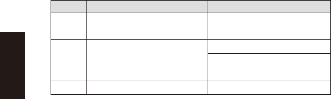
Position Name Part Name Part No. Note Qty
X/Y-axis
Y-axis cable carrier chain links
LINK, 70 CABLE Y KMB-M26H1-00X
4-beam type
Set per machine
1
LINK, 90 CABLE Y KMB-M26H1-10X
2-beam type
Set per machine
1
Vacuum pump
Vacuum pump maintenance
set
PUMP SPARE SET
KLF-M86P0-00X
For a 4-beam type machine
(2 pumps)
1
KLF-M86P0-10X
For a 2-beam type machine
(1 pump)
1
Ionizer
(option)
Ionizer discharge needle set
(4 per set)
Needle Set KHN-M83P1-00X 1
*4
UPS
(option)
UPS battery UPS,BATTERY KGA-M6566-30X 1
*1
Required quantity per head unit
*2
Required quantity for each lane
*3
Required quantity per machine when one side is extended
*4
Required quantity per ionizer