00194081-01.pdf - 第106页
3 Technical data User Manual SIP LACE CF 3.12 Magnetic pin support Software Version SR. 408.xx 03/2006 US Edition 106 3.12 Magnetic pin suppor t Item no. 001 1 9680- xx Wide boar ds tend to de flect dur ing placeme nt su…

User Manual SIPLACE CF 3 Technical data
Software Version SR.408.xx 03/2006 US Edition 3.11 PCB conveyor
105
3.11.2 Technical data
3
PCB format
(length x width)
50 mm x 50 mm to 508 mm x 460 mm
(2" x 2" to 20" x 18")
Long board: length up to 610 mm (24") (available upon
request)
PCB thickness 0.5 mm to 4.5 mm
Max. PCB warpage Up: 4.5 mm - PCB thickness
Down: 0.5 mm + PCB thickness
Clearance on PCB underside 25 mm (standard), 40 mm (option)
PCB transport height 830 mm ± 15 mm (standard)
900 mm ± 15 mm (optional)
930 mm ± 15 mm (optional)
950 mm ± 15 mm (SMEMA: optional)
Fixed conveyor side Right (standard), left (optional)
Type of interface Siemens
SMEMA
Component-free PCB handling edge 3 mm
PCB changeover time 2.5 s
Bad fiducial detection Possible
Automatic width adjustment Possible
3 Technical data User Manual SIPLACE CF
3.12 Magnetic pin support Software Version SR.408.xx 03/2006 US Edition
106
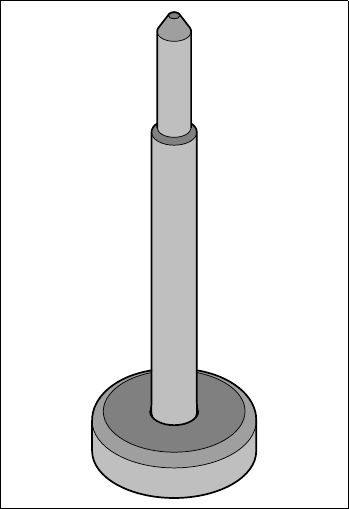
3.12 Magnetic pin support
Item no. 00119680-xx
Wide boards tend to deflect during placement such that, under certain circumstances, the compo-
nents can no longer be placed with the desired accuracy. Highly curved PCBs also affect the
placement accuracy. This problem can be easily rectified by fitting magnetic pin supports on the
lifting table.
3
Fig. 3.12 - 1 Magnetic pin support
User Manual SIPLACE CF 4 Setting up the placement system
Software Version SR.408.xx 03/2006 US Edition 4.1 Transport configuration and infrastructure
107
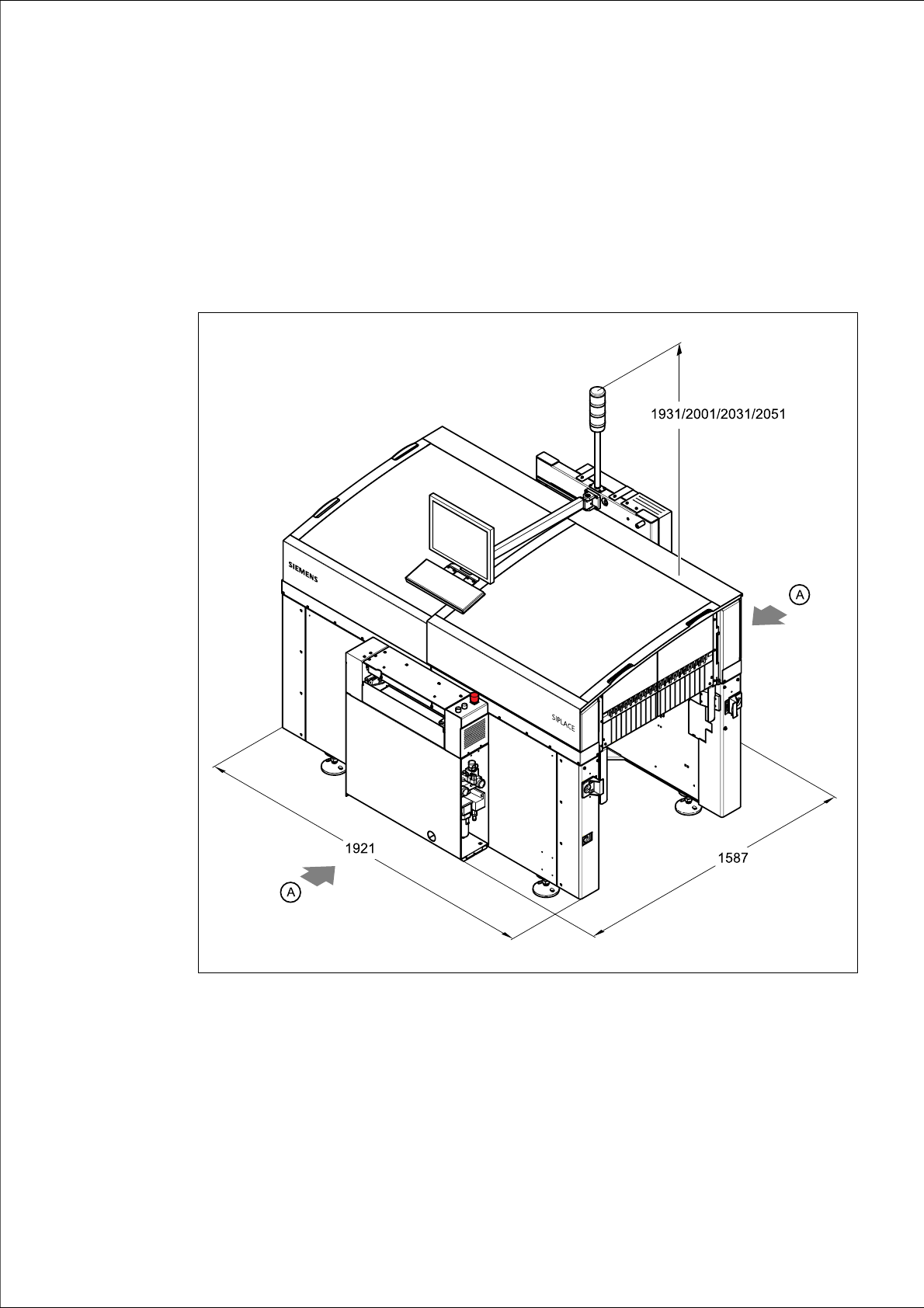
4 Setting up the placement system
4.1 Transport configuration and infrastructure
4
Fig. 4.1 - 1 Dimensions of the placement system during transportation and setting up in millimeters
4
(A) Points for attaching the fork-lift truck (fork length 1600 mm)
(1) Input conveyor
(2) Output conveyor