00194081-01.pdf - 第159页
User Manual SIPLAC E CF 6 Component han dling Software Version SR.408.xx 03/2006 US Edition 6.2 Technical data for the S feeder modules 159 6.2.19 Dip module 6 Fig. 6.2 - 19 Dip module (1) Dip modul e (2) Rotating pl ate…
6 Component handling User Manual SIPLACE CF
6.2 Technical data for the S feeder modules Software Version SR.408.xx 03/2006 US Edition
158
PLEASE NOTE 6
The support for the waffle-pack magazine must only be placed on the right-hand side of the SI-
PLACE CF. It can only be positioned so that the right edge fills no more than track 73. 6
6.2.18.1 Assembly
Æ Insert the front side of the waffle-pack tray holder into the associated centering pin (A in Fig.
6.2 - 18
).
Æ Then position the hole on the rear side of the waffle-pack tray holder onto the centering ball on
the component feeder table (B in Fig. 6.2 - 18
).
Æ Make sure the waffle-pack tray is resting securely on the component feeder table.
Æ Position one side of the waffle-pack tray carrier in the mounting (C in Fig. 6.2 - 18). Then press
the other side into the mounting (D in Fig. 6.2 - 18
).
Æ Slide the waffle-pack tray up against the stop (E in Fig. 6.2 - 18).
Æ Secure the waffle-pack tray carrier by pressing the thrust pad (F in Fig. 6.2 - 18) downwards.
Æ To remove the waffle-pack tray carrier, press the thrust pad once more.
PLEASE NOTE
Using the holder for small waffle-pack trays (136mm) a waffle-pack tray (JEDEC or CENELEC
waffle-pack tray) can be fitted directly to the holder, in other words, without a waffle-pack tray car-
rier being used. However, the thrust pad will require changing.
WARNING
All locations must be equipped with feeder modules in order to guarantee operational reliability.
If there are not enough feeder modules available, unassigned locations should be fitted with a
hand guard (dummy feeder module). When a waffle-pack tray holder is set up, the remaining
locations have to be protected again with a hand guard.
6.2.18.2 Changing the retainer
Æ Hold the retainer (G in Fig. 6.2 - 18) firmly. Press the thrust pad downwards (F in Fig. 6.2 - 18)
and remove the retainer by pressing it out sideways.
6.2.18.3 Data entry
Define the waffle-pack trays as described in the SIPLACE Pro operating instructions.
User Manual SIPLACE CF 6 Component handling
Software Version SR.408.xx 03/2006 US Edition 6.2 Technical data for the S feeder modules
159
6.2.19 Dip module
6
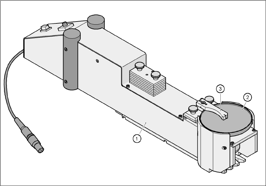
Fig. 6.2 - 19 Dip module
(1) Dip module
(2) Rotating plate
(3) Squeegee
6.2.19.1 Principle of dip fluxing
The dip module (item 1) is used to wet flip-chip and CSP components with flux or conductive ad-
hesive. The flux holder is a rotating plate (item 2) on which a thin film of flux (e.g. 40 µm) is created
with a squeegee (item 3). This method is particularly suitable for highly viscous (honey-like) fluxes.
The amount of flux required for the process is reduced to a minimum coating thickness since only
the undersides of the bumps have to be wetted.
The dip module is suitable for all placement heads. It is regarded as a standalone type of conveyor
by the set-up optimization. There is no limit to the number of dip modules at the individual loca-
tions.
6 Component handling User Manual SIPLACE CF
6.2 Technical data for the S feeder modules Software Version SR.408.xx 03/2006 US Edition
160
6.2.19.2 Technical data
Item no. 00117010-xx 6
Assigned locations 3 6
Component size Max. 36 x 36 mm²
depending on the placement head type 6
Possible coating thicknesses 25, 35, 45, 55, 65, 75 µm 6
Time required to change the coating thickness Less than 1 min. 6
Gap height tolerance ± 5 mm 6
Plate rotating speed Programmable from 0 - 10 sec.
in 0.1 sec. increments 6
Component dip time Programmable from 0 - 2 sec.
in 0.1 sec. increments 6
Flux Highly viscous flux, conductive adhesive 6