00194081-01.pdf - 第170页
6 Component handling User Manual S IPLACE CF 6.5 Waffle-pack changer Software Version S R.408.xx 03/2006 US Edition 170 6 Fig. 6.5 - 3 Sequence of functions 6 (1) The Lift of the maga zine stor age unit pos itions th e s…
User Manual SIPLACE CF 6 Component handling
Software Version SR.408.xx 03/2006 US Edition 6.5 Waffle-pack changer
169
6
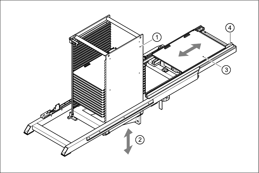
Fig. 6.5 - 2 Principle of the waffle-pack changer
6
(1) Magazine storage unit
(2) Lift
(3) Magazine
(4) Horizontal axis
6.5.3.1 Sequence of functions
Waffle-pack trays with the associated components are defined in the set-up. Once the set-up has
been converted, the magazine storage unit performs a reference run.
6 Component handling User Manual SIPLACE CF
6.5 Waffle-pack changer Software Version SR.408.xx 03/2006 US Edition
170
6
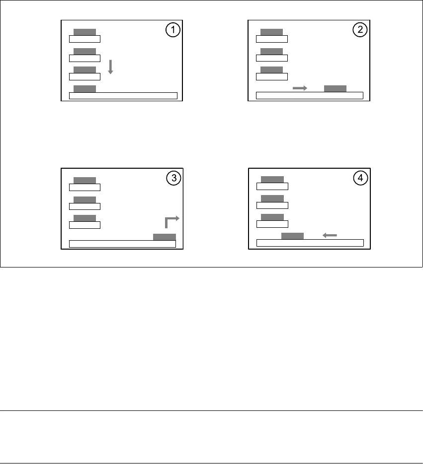
Fig. 6.5 - 3 Sequence of functions
6
(1) The Lift of the magazine storage unit positions the selected magazine carriers level with the
horizontal feed axis.
(2) The magazine carrier is carried to the placement head's pick-up area.
(3) The components are removed.
(4) The magazine carrier is moved back into the magazine storage unit.
6
PLEASE NOTE 6
If the placement sequence is interrupted thus switching off the waffle-pack changer, the set-up and
the current fill level are stored. 6
The position of the waffle-pack tray carrier in the waffle-pack tray storage unit and the components
to be placed in the waffle-pack tray carrier are entered in the set-up.
The waffle-pack changer is defined as location 1.
User Manual SIPLACE CF 6 Component handling
Software Version SR.408.xx 03/2006 US Edition 6.5 Waffle-pack changer
171
6.5.4 Inserting the magazine carrier
The magazine carrier is checked to ensure that it was inserted correctly.
6
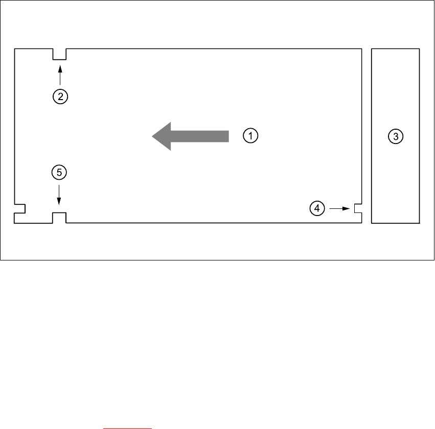
Fig. 6.5 - 4 Position of the magazine carrier - plan view
6
(1) Transport direction
(2) Driving groove
(3) Magazine storage unit
(4) Control groove
(5) Driving groove
6
Make sure that the driving grooves (item 2 and 5) of the magazine carrier point forward in the
direction of travel (see Fig. 6.5 - 4
).
The control grooves (item 4) of the individual magazine carriers must be above one another and
point towards the magazine storage unit (item 3).