00194081-01.pdf - 第178页
7 Station extensions User Manual S IPLACE CF 7.1 Nozzle changer for the Pick&Place head Software Version S R.408.xx 03/2006 US Edition 178 The place ment machi ne is equipp ed with a nozzle ch anger for the Pick&…
User Manual SIPLACE CF 7 Station extensions
Software Version SR.408.xx 03/2006 US Edition 7.1 Nozzle changer for the Pick&Place head
177
7 Station extensions
7.1 Nozzle changer for the Pick&Place head
7.1.1 Overview
7
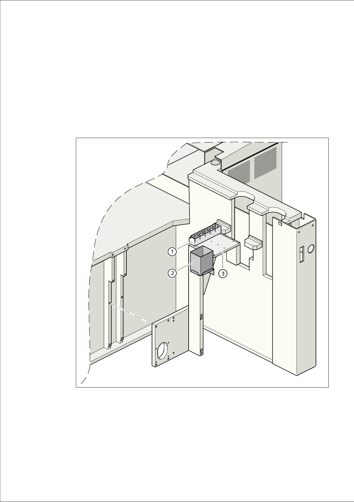
Fig. 7.1 - 1 Installation location of the nozzle changer for the Pick&Place head
(1) Magazine for 5 nozzles
(2) Reject bin
(3) Support plate

7 Station extensions User Manual SIPLACE CF
7.1 Nozzle changer for the Pick&Place head Software Version SR.408.xx 03/2006 US Edition
178
The placement machine is equipped with a nozzle changer for the Pick&Place head as standard.
It is supplied with a nozzle magazine for five nozzles, for example four standard nozzles from the
4xx series and one special nozzle. Three additional nozzle magazines may be retrofitted if
required, providing up to 20 nozzles.
Each nozzle magazine (see item 4 in Fig. 7.1 - 2
) is centered with two parallel pins, and is fixed
to the support plate with a countersunk screw (see item 6 in Fig. 7.1 - 2
). Nozzles are changed
automatically during the placement process.
7.1.2 Technical data
7
Nozzle changer for the Pick&Place head
Nozzle types All nozzles from the 4xx series, special nozzle (optional)
Capacity 1 to 4 magazines, each with 5 nozzles, may be configured as
required
Nozzle changeover time Approx. 2 sec. per nozzle
User Manual SIPLACE CF 7 Station extensions
Software Version SR.408.xx 03/2006 US Edition 7.1 Nozzle changer for the Pick&Place head
179
7.1.3 Description of the functions
7
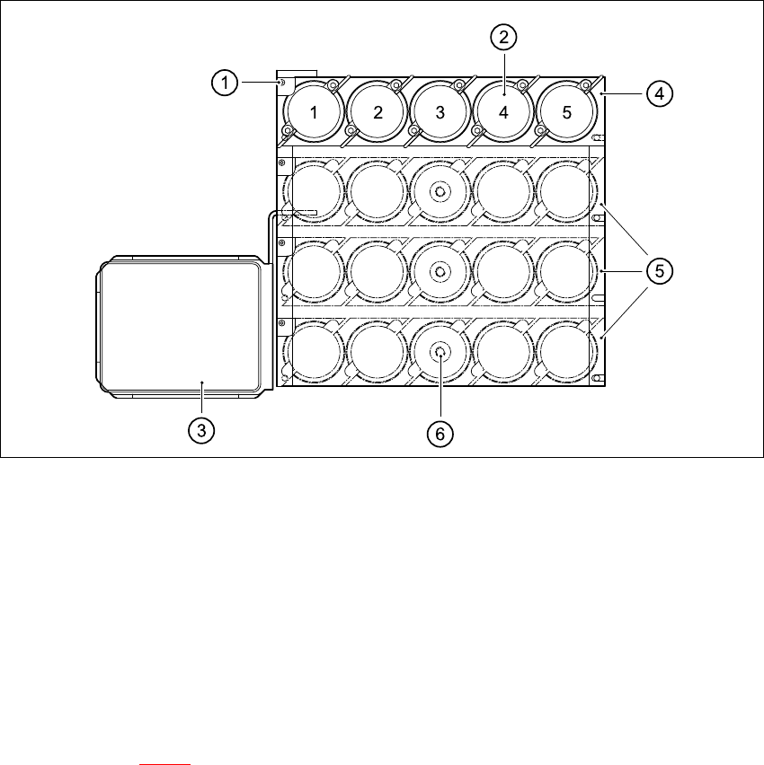
Fig. 7.1 - 2 Nozzle changer overview
(1) Positioning fiducial
(2) Nozzle holder
(3) Reject bin
(4) Magazine 1 (standard)
(5) Magazine 2 to 4 (optional)
(6) Countersunk screw
7
– There is a positioning fiducial for position detection on each magazine of the nozzle changer
(item 1 in Fig. 7.1 - 2
).
– The individual locations are numbered consecutively from 1 to 4.
– The individual nozzle garages in the individual magazines are numbered consecutively from 1
to 5.
– the nozzles are fixed in position in the holder using sprung hooks. The nozzles are either
clamped or released according to the direction of rotation of the Pick&Place head axis.