00194081-01.pdf - 第182页
7 Station extensions User Manual S IPLACE CF 7.2 Flip-chip vision m odule for the Pick &Place head Software V ersion SR.408.xx 03/2006 US E dition 182 7.2.1 Description of the functions The flip -chip vision module i…
User Manual SIPLACE CF 7 Station extensions
Software Version SR.408.xx 03/2006 US Edition 7.2 Flip-chip vision module for the Pick&Place head
181
7.2 Flip-chip vision module for the Pick&Place head
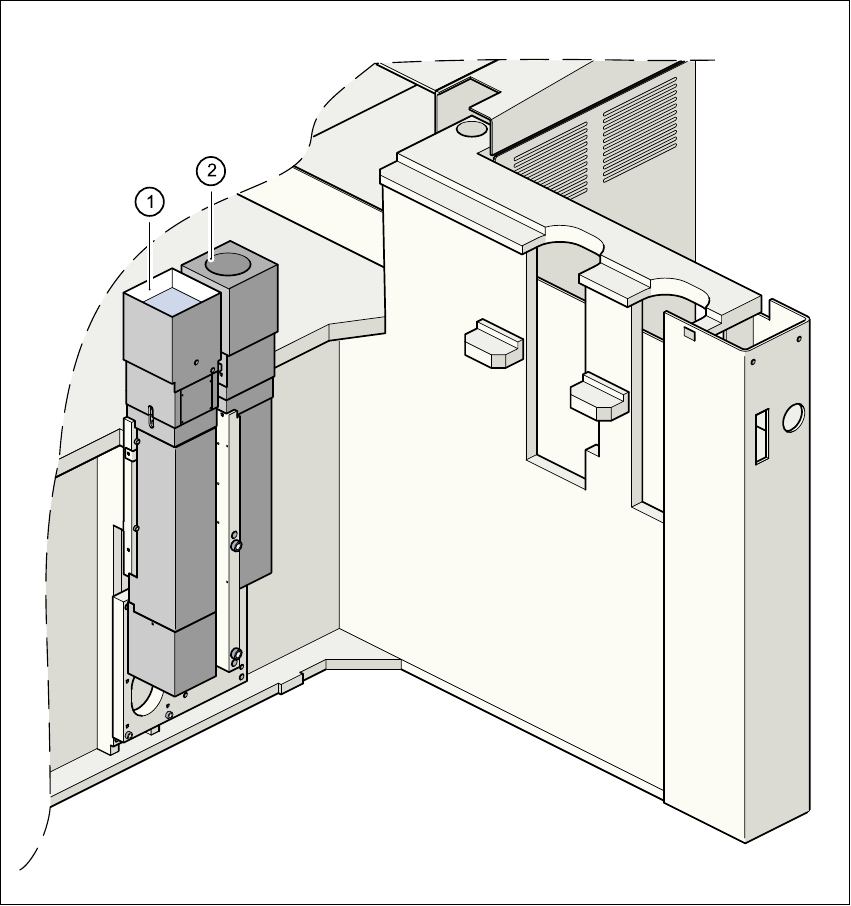
Fig. 7.2 - 1 Vision module for the Pick&Place head
(1) Fine-pitch vision module for the Pick&Place head
(2) Flip-chip vision module for the Pick&Place head
7 Station extensions User Manual SIPLACE CF
7.2 Flip-chip vision module for the Pick&Place head Software Version SR.408.xx 03/2006 US Edition
182
7.2.1 Description of the functions
The flip-chip vision module increases the capability for processing fine-pitch and flip-chip compo-
nents with extremely fine lead pitches. This add-on module for the fine-pitch vision module
increases the resolution many times. The lighting layout is fundamentally different. At optimal illu-
mination, the images of bumps are as large as possible, and disruptive orthogonal structures (as
can occur on chip printed conductor tracks, for example) are suppressed. With less pronounced
disruptive structures, enhanced illumination intensity can be achieved by combining lighting fix-
tures resulting in high recognition reliability, even with the generally square connection surfaces
of ‘bumped’ flip-chips as used in conductive adhesive technology. Special search algorithms are
used to recognize the bumps in environments subject to disruption.
7.2.2 Safety instructions for the component vision modules on the CF machine
DANGER
NEVER modify or bypass safety devices on the CF machine, or on the fine-pitch or flip-chip mod-
ule. 7
The optical radiation from the fine-pitch or flip-chip vision module conforms to laser class 1,
provided that the module is permanently installed in the placement machine, and the protective
hoods are closed
(EN 60825-1 or IEC 825).
Fig. 7.2 - 2 Identification for laser class 1
Laser class 1

User Manual SIPLACE CF 7 Station extensions
Software Version SR.408.xx 03/2006 US Edition 7.2 Flip-chip vision module for the Pick&Place head
183
7.2.3 Technical data
Flip-chip size
With single measurement
With multiple measurement
1x1 mm
Up to 7 x 9 mm
Up to 20 mm x 20mm
Dimensions < 3mmx6mm Special nozzle, feeding tolerance < 0.2 mm edge length
Min. bump diameter 80µm
Placement cycle minimum 2 sec (depending on the number of bumps)
IC pitch:
Lead pitch
Bump pitch
0.25 mm
0.15 mm
Field of vision 9 mm x 11.5 mm
Method of illumination Front lighting (three levels, programmable as required)