00194081-01.pdf - 第191页
User Manual SIPLAC E CF 7 Station extensions Software Vers ion SR.408.xx 03/2006 US Ed ition 7.4 DCA vision cam era 191 7.4.3 Descri ption The 6-seg ment Co llect & Place h ead ca n optical ly center and plac e compo…
7 Station extensions User Manual SIPLACE CF
7.4 DCA vision camera Software Version SR.408.xx 03/2006 US Edition
190
7.4 DCA vision camera
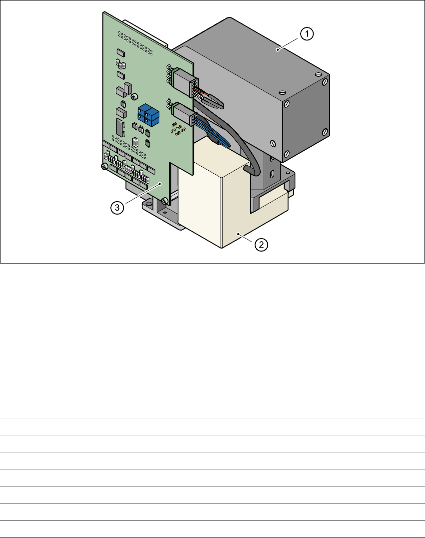
7.4.1 Structure
7
Fig. 7.4 - 1 DCA vision camera
7
(1) DCA vision camera, lens and illumination
(2) Camera amplifier
(3) Illumination control
7
7.4.2 Technical data - DCA vision camera
7
7
Component dimensions 0.6 mm x 0.3 mm to 13 mm x 13 mm
Range of components 0201 up to 13 mm x 13 mm flip-chips, bare die
Min. lead pitch 0.4 mm
Min. bump pitch 0.2 mm
Min. ball/bump diameter 0.11 mm
Field of vision 15.7 mm x 15.7 mm
Method of illumination Front lighting (four levels, programmable as required)

User Manual SIPLACE CF 7 Station extensions
Software Version SR.408.xx 03/2006 US Edition 7.4 DCA vision camera
191
7.4.3 Description
The 6-segment Collect&Place head can optically center and place component sizes from 0.6x
0.3mm² to 13 x 13 mm² using the DCA vision module. The DCA package optimizes the speed
and accuracy when placing high-speed flip-chips and bare die components. 7
7.4.4 Technical data - 6-segment Collect&Place head with DCA camera
Component range 0201 up to 13 mm x 13 mm
Component specification
Max. height
Min. lead pitch
Min. bump pitch
Min. ball/bump diameter
Min. dimensions
Max. dimensions
Max. weight
6 mm
0.4 mm
0.2 mm
0.11 mm
0.6 mm x 0.3 mm
13 mm x 13 mm
2 g
Programmable set-down force 2.4 to 5.0 N
Nozzle types 9 xx
Max. placement rate 9,000 comp/h
Angular accuracy ± 0.5° / 3 σ ± 0.7° / 4 σ
Placement accuracy ± 68 µm / 3 σ ± 90 µm / 4σ
7 Station extensions User Manual SIPLACE CF
7.5 Multicolor PCB camera (type 18) Software Version SR.408.xx 03/2006 US Edition
192
7.5 Multicolor PCB camera (type 18)
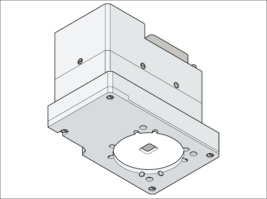
7.5.1 General
As an option, a multicolor PCB camera can be installed in place of the sub-gantry camera. The
multicolor PCB camera offers four different types of illumination. This greatly increases fiducial de-
tection and thus the centering accuracy.
7
Fig. 7.5 - 1 Multi-color PCB camera
7.5.2 Type of illumination
The following types of illumination can be selected on the multicolor PCB camera:
– Standard lighting
This mixture of white and infrared lighting can be used to detect a broad range of fiducials.
The image contrast can be improved by varying the illumination, thus optimizing the centering
of different fiducials.