00194081-01.pdf - 第66页
3 Technical data User Manual SIP LACE CF 3.1 Description of the m achine Software Version S R.408.xx 03/2006 US Edition 66 The placeme nt heads pi ck up com ponents from stationa ry feeders and use them to populate th e …
User Manual SIPLACE CF 3 Technical data
Software Version SR.408.xx 03/2006 US Edition 3.1 Description of the machine
65
3 Technical data
3.1 Description of the machine
The placement machine is a high-performance placement system with one gantry. It holds a 6-
segment Collect&Place head, a Pick&Place head and a PCB camera.
3
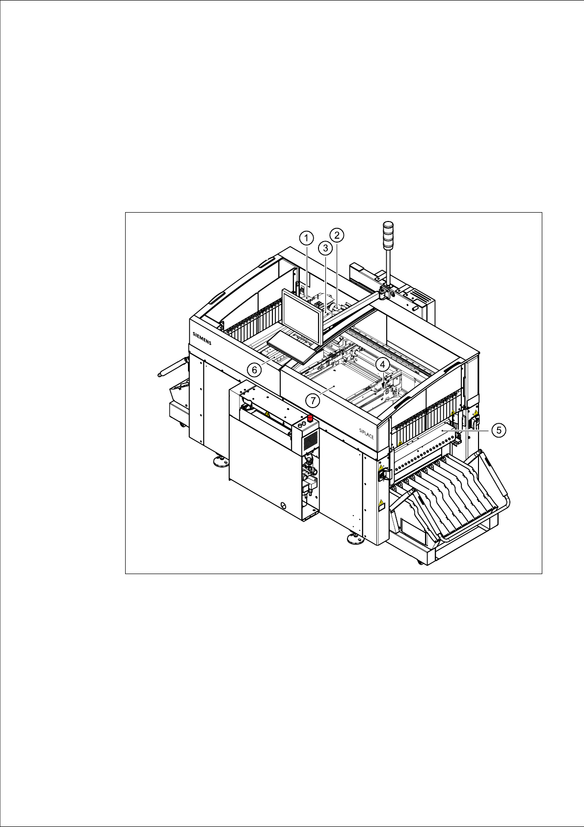
Fig. 3.1 - 1 Overall view of the placement system
(1) 6-segment Collect&Place head with component camera
(2) Gantry 1 with PCB camera
(3) Pick&Place head
(4) Fine-pitch camera for the Pick&Place head
(5) Stationary component supply (location 1)
(6) Stationary component supply (location 3)
(7) PCB conveyor
3 Technical data User Manual SIPLACE CF
3.1 Description of the machine Software Version SR.408.xx 03/2006 US Edition
66
The placement heads pick up components from stationary feeders and use them to populate the
PCB clamped on the PCB conveyor.
The 6-segment Collect&Place head equipped with a component camera can process size 0201
to 18.7 mm x 18.7 mm components.
The Pick&Place head is particularly suitable for placing fine pitch components. It places compo-
nent sizes ranging from 1.6 mm x 0.8 mm to 55 mm x 55 mm. In addition to the PCB centering
vision module, the placement machine also has component vision modules for the Collect&Place
head and Pick&Place head.
The concept behind the automatic placement system
– with its stationary feeders,
– PCBs that do not move during placement
– and positionable placement heads
has a number of significant benefits:
– For example, the flexible 6-segment Collect&Place head combined with automatic nozzle
changer enables the nozzle configuration to be changed temporarily and automatically
adapted to receive different component sizes. The same applies to the Pick&Place head. You
can also optimize the traversing paths and the placement sequence.
– With stationary feeders, even the tiniest components are picked up reliably.
– The components cannot slip on the PCB during placement (as is often the case with moving
PCBs) since the PCB does not move.
– Sophisticated optical centering systems (vision modules) for components and PCBs also en-
sure high component positioning accuracy.
– Components can be topped up and tapes can be spliced without stopping the machine.
– Prepared component trolleys enable the placement system to be retooled without long stop-
pages.
A waffle-pack changer may be used to supply components.
User Manual SIPLACE CF 3 Technical data
Software Version SR.408.xx 03/2006 US Edition 3.1 Description of the machine
67
3
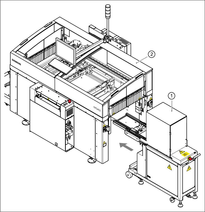
Fig. 3.1 - 2 CF overall view with waffle-pack changer
3
(1) Waffle-pack changer
(2) SIPLACE CF