00194081-01.pdf - 第69页
User Manual SIPLAC E CF 3 Technical data Software Vers ion SR.408.xx 03/2006 US Ed ition 3.2 Electrical and pneumatic connection p oints 69 3.2 Electrical and pneumatic con nection point s 3 Fig. 3.2 - 1 Electrical and p…

3 Technical data User Manual SIPLACE CF
3.1 Description of the machine Software Version SR.408.xx 03/2006 US Edition
68
3.1.1 Technical data - machine overview
3
3
3
*) The CF can be equipped to place 0201 components. Please consult the factory if you
require this.
Placement procedure Collect&Place / Pick&Place
Component range
*)
6-segment Collect&Place head
Max. component height
Pick&Place head
Max. component height
From 0.6 mm x 0.3 mm to 18.7 mm x 18.7 mm
(0201 to PLCC44, SO32, DRAM)
6 mm (10.7 mm available upon request)
Up to 55 mm x 55 mm
≤ 13.5 mm - PCB thickness - PCB warpage
(
≤ 20 mm - PCB thickness - PCB warpage available
upon request)
Maximum placement rate (Benchmark)
6-segment Collect&Place head
Pick&Place head
9.000 components/h
1.800 components/h
6-segment Collect&Place head
Angular accuracy
Placement accuracy
± 0.5° / 3 σ ± 0.7°/ 4 σ
± 68 µm / 3 σ ± 90µm / 4 σ
Pick&Place head
Angular accuracy
Placement accuracy
± 0.05° / 3σ ± 0.07°/ 4σ
± 38 µm / 3σ ± 50µm / 4σ
PCB format
(length x width) 50 mm x 50 mm to 508 mm x 460 mm
(2" x 2" to 20" x 18")
Long board: length up to 610 mm (24") (available
upon request)
PCB thickness 0.5 mm to 4.5 mm
PCB changeover time 2.5 sec
Feeder capacity 118 tracks à 8 mm
Component supply
Feeder module types
Component trolley, waffle-pack changer
Component tapes, stick magazines, bulk cases,
surf tapes and waffle-pack trays (see section 6
)
Operating system Microsoft Windows XP / RMOS
Connection Inline or stand alone
Space required 4 m² / module
User Manual SIPLACE CF 3 Technical data
Software Version SR.408.xx 03/2006 US Edition 3.2 Electrical and pneumatic connection points
69
3.2 Electrical and pneumatic connection points
3
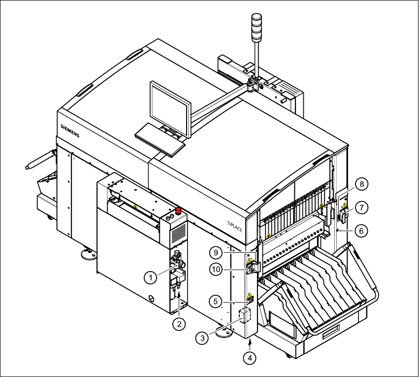
Fig. 3.2 - 1 Electrical and pneumatic connection points on the placement system - part 1
(1) Compressed air unit
(2) Connection for compressed air line
(3) Main power filter Z1
(4) Hole for power cable
(5) Service socket
(6) Compressed air connection for component trolleys
(7) Power supply connection for component trolley
(8) Communications connection for component trolley
(9) Communications connection for waffle-pack changer
(10) Power supply connection for waffle-pack changer
3 Technical data User Manual SIPLACE CF
3.2 Electrical and pneumatic connection points Software Version SR.408.xx 03/2006 US Edition
70
WARNING
NEVER detach compressed air lines while they are still pressurized. Risk of injury! 3
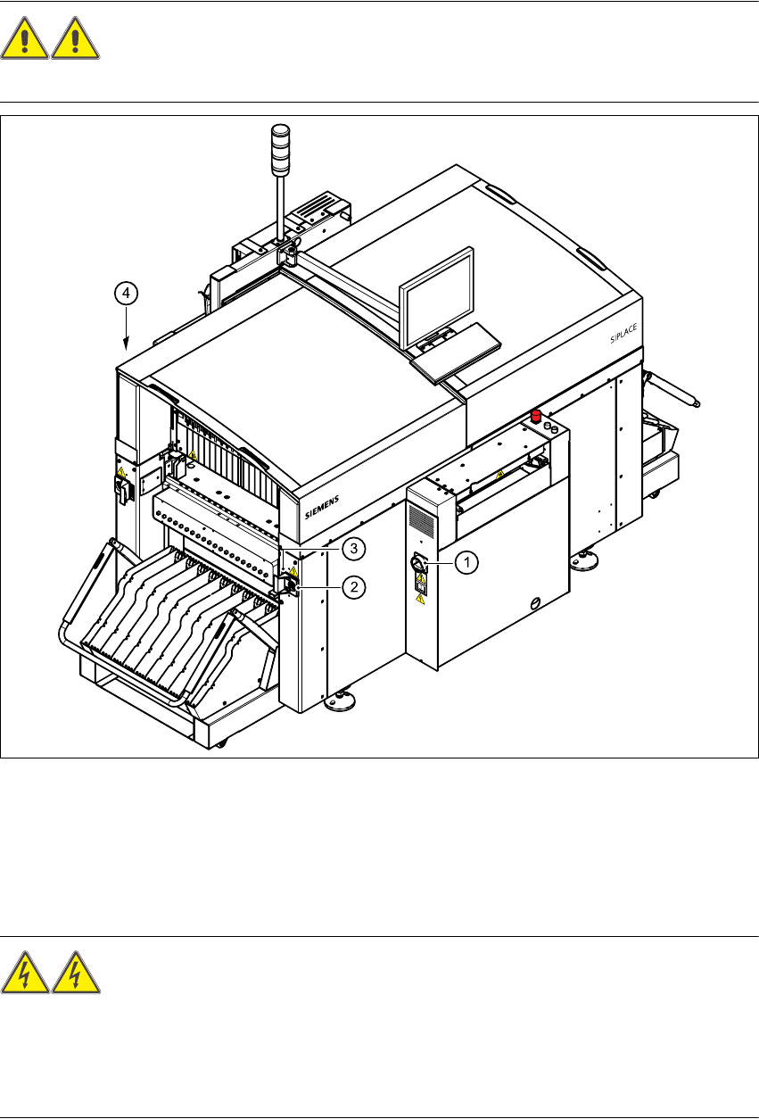
Fig. 3.2 - 2 Electrical and pneumatic connection points on the placement system - part 2
(1) Main power switch
(2) Power supply connection for component trolley
(3) Communications connection for component trolley
(4) LAN connection (RJ45) in the control unit
WARNING
The placement system is supplied with 3 x 400 V~ or 3 x 208 V~ US version) ± 5%, 50/60 Hz
main power voltage. This means that some parts of the system carry potentially lethal voltages
- even when switched off at the main power switch. Death, serious injury or considerable damage
may result if this automatic placement system is handled incorrectly. 3