00194081-01.pdf - 第94页
3 Technical data User Manual SIP LACE CF 3.9 Vision modules Software Version S R.408.xx 03/2006 US Edition 94 3.9.3 Fine-pit ch camera for t he Pick&Pla ce head 3 Fig. 3.9 - 2 Fine-pitch cam era for t he Pick&Pla…
User Manual SIPLACE CF 3 Technical data
Software Version SR.408.xx 03/2006 US Edition 3.9 Vision modules
93
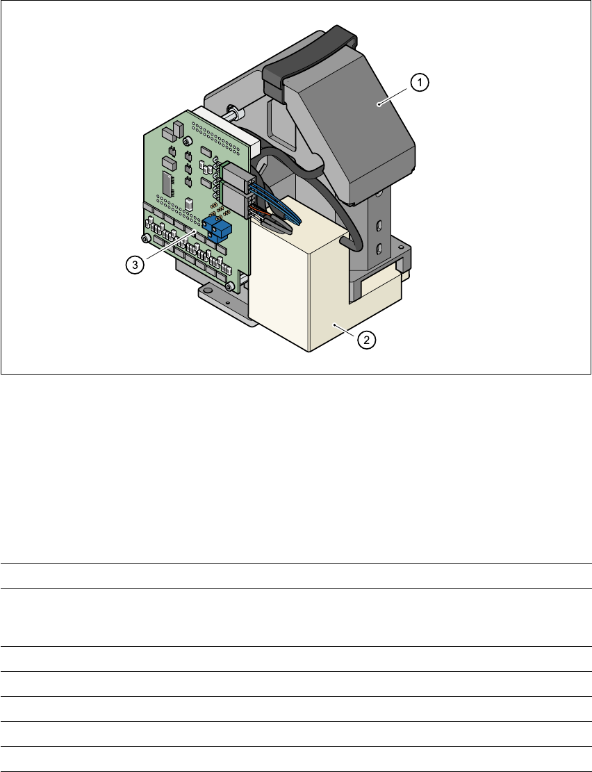
3.9.2 Component vision camera (standard camera) on the 6-segment
Collect&Place head
3.9.2.1 Structure
3
Fig. 3.9 - 1 Component camera (standard camera) on the 6-segment Collect&Place head
3
(1) Component camera, lens and illumination
(2) Camera amplifier
(3) Illumination control
3.9.2.2 Technical data
3
Max. component dimensions 0.6 mm x 0.3 mm to 18.7 mm x 18.7 mm
Range of components 0201 to PLCC44
including BGA, µBGA, flip-chip, TSOP, QFP
PLCC, SO to SO32, DRAM
Min. lead pitch 0.5 mm
Min. bump pitch 0.35 mm
Min. ball/bump diameter 0.2 mm
Field of vision 24 mm x 24 mm
Method of illumination Front-lighting (3 levels, programable as required)
3 Technical data User Manual SIPLACE CF
3.9 Vision modules Software Version SR.408.xx 03/2006 US Edition
94
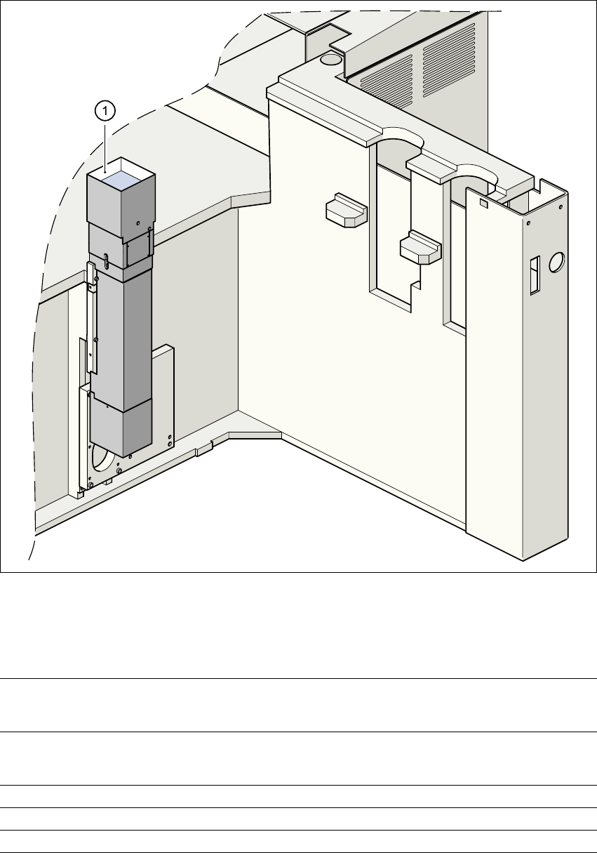
3.9.3 Fine-pitch camera for the Pick&Place head
3
Fig. 3.9 - 2 Fine-pitch camera for the Pick&Place head
(1) Fine-pitch camera for the Pick&Place head
3.9.3.1 Technical data
3
Max. component dimensions 32 mm x 32 mm (single measurement)
55 mm x 55 mm (multiple measurement)
(larger components possible upon request)
Range of components PLCC, LCCC, QFP, SO, BGA, flip-chip,
components with connectors up to 55 mm x 55 mm
(J leads and gull-wings, balls, bumps)
Min. lead pitch 0.4 mm
Field of vision 38 mm x 38 mm
Method of illumination Front-lighting (3 levels, programable as required)
User Manual SIPLACE CF 3 Technical data
Software Version SR.408.xx 03/2006 US Edition 3.9 Vision modules
95
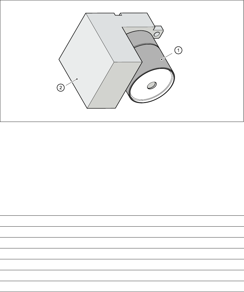
3.9.4 PCB vision camera (standard camera)
3.9.4.1 Structure
3
Fig. 3.9 - 3 PCB camera
3
(1) PCB camera, lens and illumination
(2) Camera amplifier
3.9.4.2 Technical data - PCB vision camera
3
Fiducials Up to 3 (subpanels and multiple panels)
Local fiducials Up to 2 per PCB (may be of different types)
Library size Up to 255 fiducial types - system fiducials ≥ 249
Image processing Geometric alignment
Method of illumination Front-lighting
Detection time per fiducial/bad fiducial 0.4 s
Field of vision 5.7 mm x 5.7 mm