P-TOOL说明书.pdf - 第162页
3-42 3 Board Editor 3.2 Manipulating the graphic view The graphic view consists of a graphic window and a toolbar. Graphic view screen Graphic toolbar Board graphic window 64349-S0-00 ● Graphic toolbar 1 2 3 5 4 6 7 8 9 …
3-41
3
Board Editor
3. Graphic View
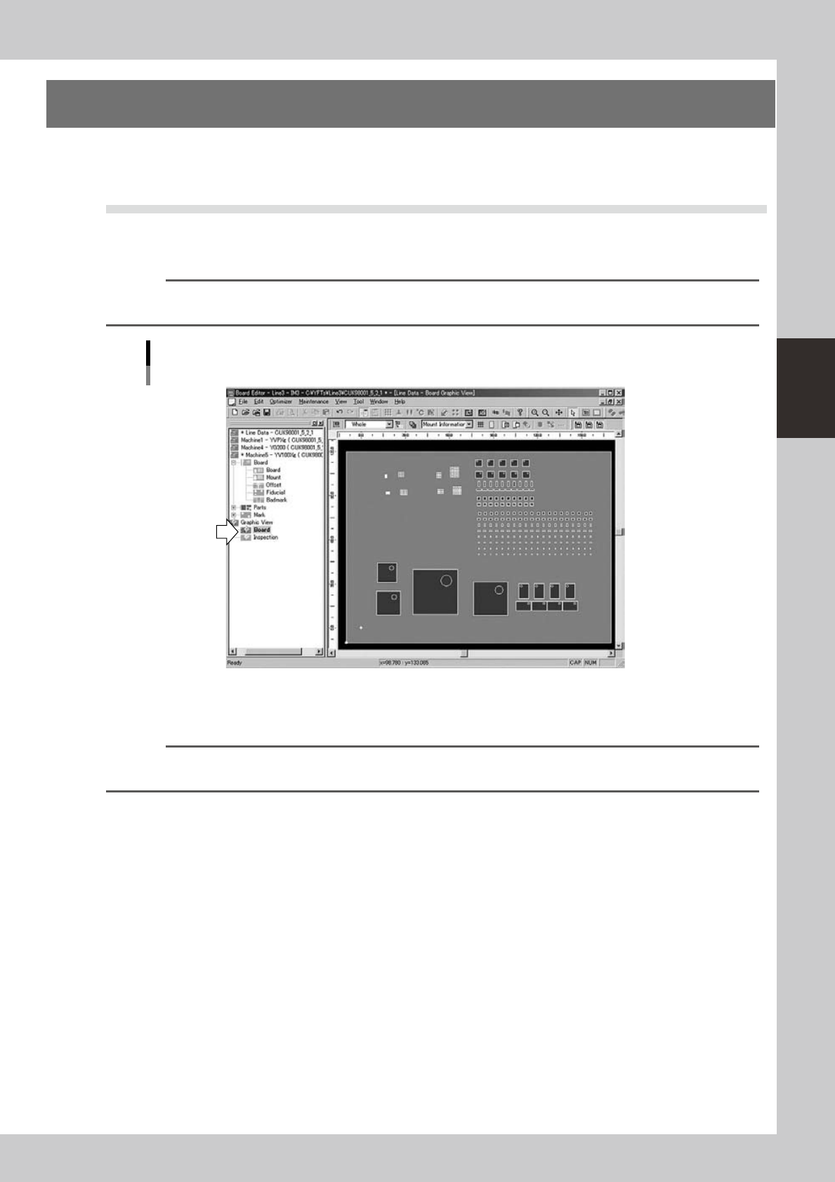
The graphic view graphically displays component placement layout and fiducial mark positions in the main
view as well as component and mark outlines.
3.1 Displaying/closing the graphic view
●
Displaying the graphic view
To display the graphic view when not displayed, click the Graphic View icon in the tree view.
Reference
Selecting "Graphic View" from the View menu or clicking the [Show Graphic View] button on the toolbar also displays
the graphic view.
Graphic view
64348-S0-00
●
Closing the graphic view
To close the graphic view when being displayed, click an icon other than the Graphic View icon in the tree view.
Reference
Selecting "Graphic View" from the View menu or clicking the [Show Graphic View] button on the toolbar also closes
the graphic view.
3-42
3
Board Editor
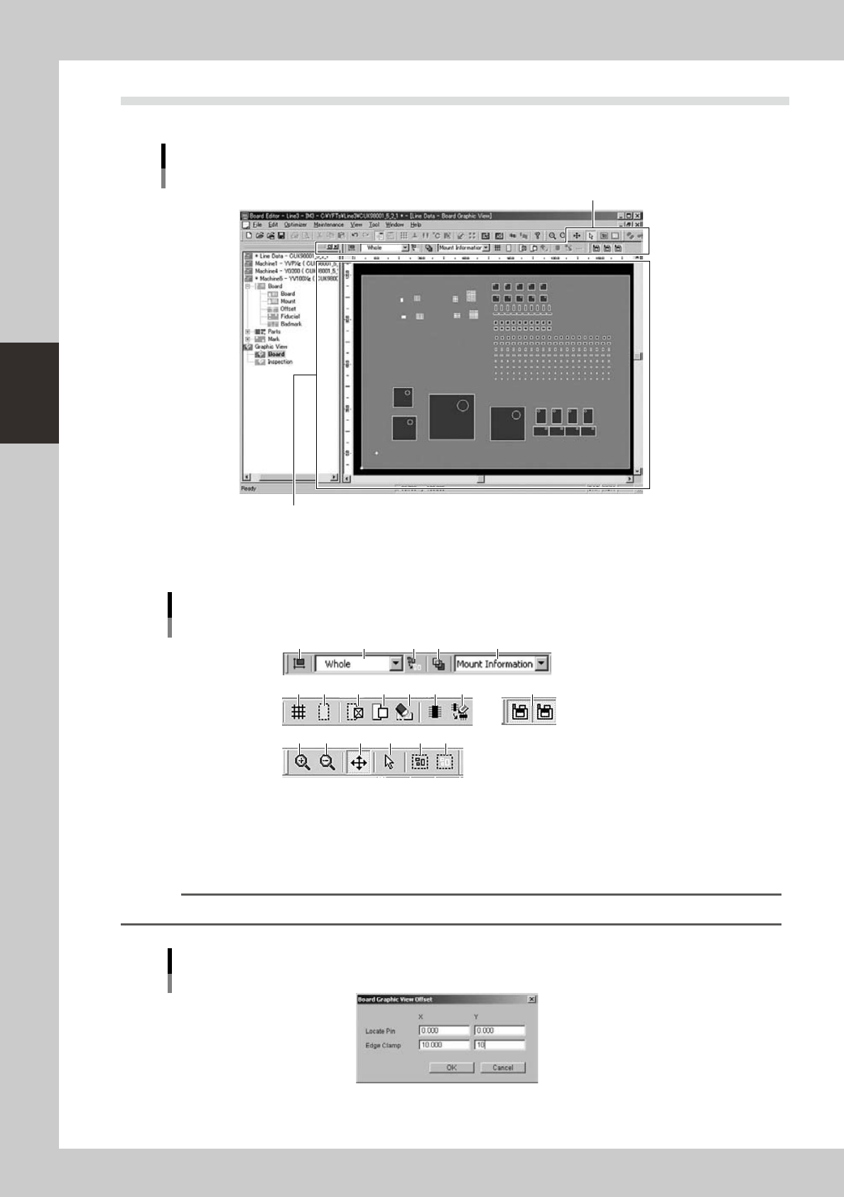
3.2 Manipulating the graphic view
The graphic view consists of a graphic window and a toolbar.
Graphic view screen
Graphic toolbar
Board graphic window
64349-S0-00
●
Graphic toolbar
1 2 3 54
6 7 8 9 10 11 12 13
14 15 16 17 18 19
Graphic toolbar
64350-S0-10
1.
All offset
Setsuptheoffsetvaluefortheentiregraphicviewindication.(Referto3.4Graphicviewindicationoffsetsetting)
Select a board securing method and enter the origin position of board in the respective fields. Click the [OK] button to
close the window and the values will be applied to the graphic view.
Reference
The origin position of board is usually shown at the position of X=5mm, Y=5mm on the graphic view.
Indication offset
64351-S0-00
3-43
3
Board Editor
2.
Magnification drop-down list
Thegraphicviewcanbeexpandedorreducedasneeded.Selectthedesiredmagnificationfromthe“Zoom”drop-down
list. In this case, the top right corner of the Board is used as the reference point
3. [Deselect All] button
Cancels the selection of all objects in the graphic view. (Each object in the graphic view can be selected when the
[Select] button is pressed.)
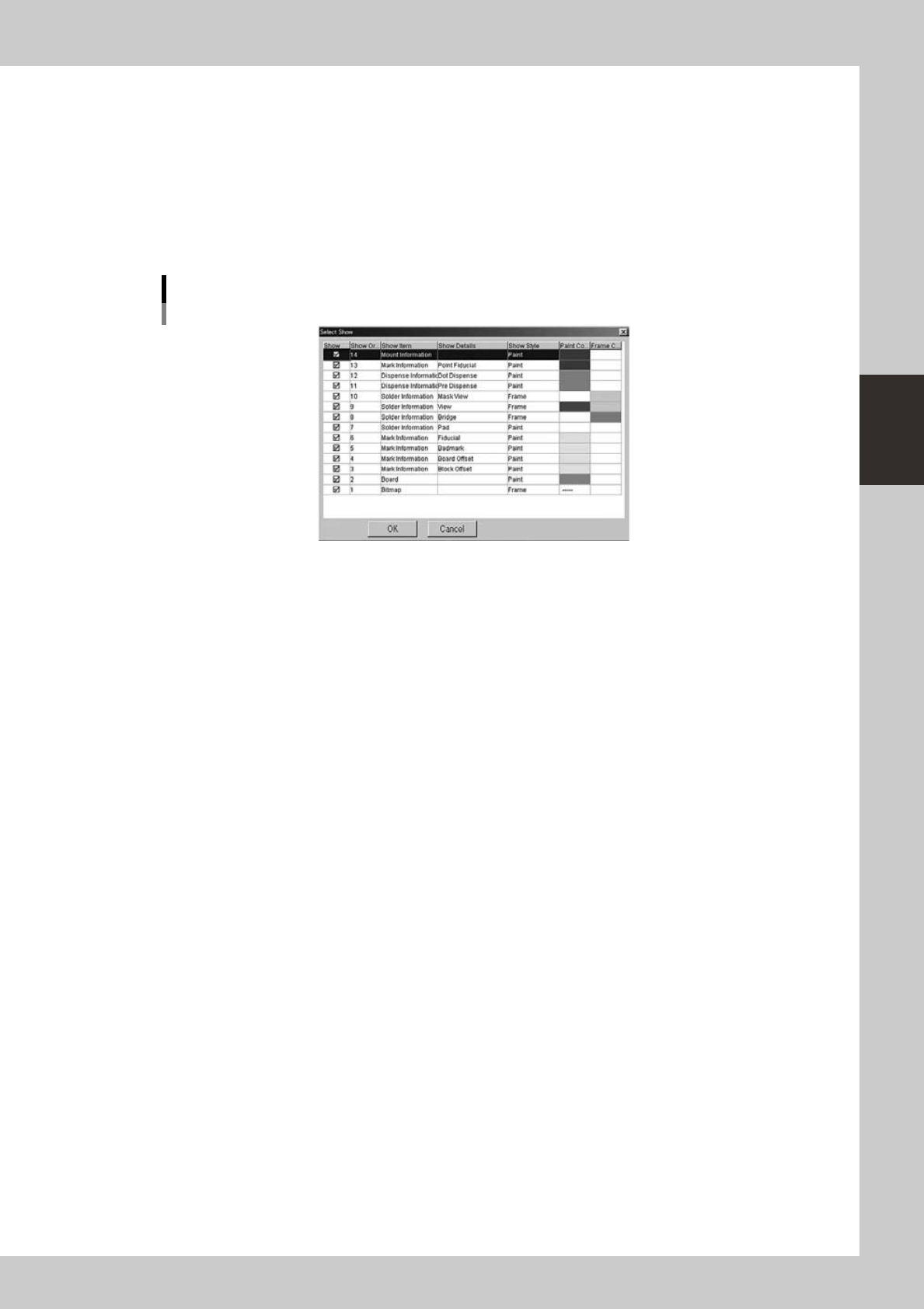
4. [Edit Display Color] button
Opens the dialog box shown below for editing the display colors.
Dialog box for editing display colors
64352-S0-00
5. Data item drop-down list
From this drop down list, select the data item you want to check and edit in the graphic view.
6. [Grid View] button
Displays grid lines in the graphic view.
7. [Skip Show/Hide] button
Shows or hides the objects set to “skip” in the mount information.
8. [Skip] button
Set the selected objects to “skip”.
9. [Skip Off] button
Cancels the “skip” setting for the selected objects.
10. [Delete Selected Items] button
Deletes the selected objects.
11. [Create New Mount Info] button
Creates new mount information.
12. [Change Mount Position] button
Changes the mount position.
13. [Select Machine] button
Selects the machine for displaying the graphic view.
14. [Zoom In] button
Enlarges the graphic view.
15. [Zoom Out] button
Reducesthegraphicview.
16. [Move] button
Moves the graphic view in the direction you drag.
17. [Select] button
Allows selecting each object in the graphic view. Selected objects are shown in a different color.
18. [Select Rectangle] button
Allows selecting objects in the graphic view by dragging to draw a rectangle.