00194398-01.pdf - 第37页
Retrofit instructions SIPLACE HS-60 12/2004 Edition 2.1 Overview 37 2 Retrofit instructions: ceramic sub- strate centering for SIPLACE HS-60 HS-60 ceramic substrate centering, sin gle conveyor (item no.: 001 19471-xx) 2 …
Nachrüstanleitung SIPLACE HS-60
1.12 Fehlermeldungen, mögliche Ursachen Ausgabe 12/2004
36
1.12 Fehlermeldungen, mögliche Ursachen
Im Fehlerfall wird folgende Fehlermeldung ausgegeben: 1
– "Fehler Keramiksubstrat-Zentrierung 1" bzw.
– "Fehler Keramiksubstrat-Zentrierung 2"
Der Bestückablauf wird dadurch angehalten. 1
Die Meldung besagt, daß das Berosignal für "geöffnet" (1) / "geschlossen" (0) nicht vorliegt.
Der Zusatz 1 bedeutet: Der Fehler besteht im Bearbeitungsbereich 1 oder 4 (siehe Fig. 1.1 - 1). 1
– Der Zusatz 2 bedeutet: Der Fehler besteht im Bearbeitungsbereich 2 oder 3 (siehe Fig. 1.1 - 1).
Mögliche Ursachen:
– Störung im Druckluftzweig / undichter Anschluß / schlechte, fehlende oder falsch zugeordnete
Steckverbindung des Magnetventilkabels am Magnetventil / Defekt des Magnetventils.
– Falscher Ansprechabstand des Näherungsschalters / Zugfeder am Flachzylinder ausgehängt,
schlechte, fehlende oder falsch zugeordnete Steckverbindung des Näherungsschalterkabels
an der X-Zentriereinheit / Defekt des Näherungsschalters.
– Falsch zugeordnete Steckverbindungen auf der Umsetzplatine (X34/X35) oder Steckverbind-
ungen für Transport 1 und 2 vertauscht.
1
1.13 Instandhaltung
: Reinigen und fetten Sie die Kugelumlaufführung in der X-Zentrierung.
: Prüfen Sie bei Bedarf den pneumatischen Antrieb auf Leichtgängigkeit.
1
Retrofit instructions SIPLACE HS-60
12/2004 Edition 2.1 Overview
37
2 Retrofit instructions: ceramic sub-
strate centering for SIPLACE HS-60
HS-60 ceramic substrate centering, single conveyor (item no.: 00119471-xx) 2
HS-60 ceramic substrate centering, dual conveyor (item no.: 00119470-xx) 2
2.1 Overview
– Ceramic substrates can be mechanically and optically centered.
The position of the fiducials on the ceramic substrates can be determined either using the sub-
gantry PCB camera with normal lighting that is installed as standard or with the optional multi-
color PCB camera.
– The mechanical ceramic substrate centering option is used to lock ceramic substrates in the X
and Y directions in a way that doesn't harm the material, but keeps them in a stable position.
– A special design allows ceramic substrates to be populated right up to the edge of the sub-
strate.
– The "mechanical ceramic substrate centering" option is only intended for use where the sta-
tionary conveyor side wall is on the right; the stationary conveyor side wall on the left is a spe-
cial design.
– The "mechanical ceramic substrate centering" option is always installed in both processing ar-
eas of the conveyor; on the dual conveyor, it is normally also installed on both PCB conveyor
tracks.
A ceramic substrate centering retrofit kit only contains the parts needed for one of the place-
ment machine's conveyor tracks.
– The appropriate stop rail and stop unit (set 1, 2 or 3) are fitted to the X axis centering unit to
adapt to the size of substrate to be processed (50 mm to 140 mm). These parts are included
in the retrofit kit in prefitted form (see Section 2.3 and Section 2.8).
– The lifting table bed must be replaced with one with holes for fixing the option (included with
the option).
– The retrofit may only be carried out by trained engineers.
– When converting to wide boards (>216 mm wide), the stationary conveyor side wall has to be
moved on the dual conveyor. The ceramic substrate centering unit must be moved in order to
do this.
Retrofit instructions SIPLACE HS-60
2.1 Overview 12/2004 Edition
38
– The ceramic substrate centering option must be removed in order to convert from dual to single
conveyor.
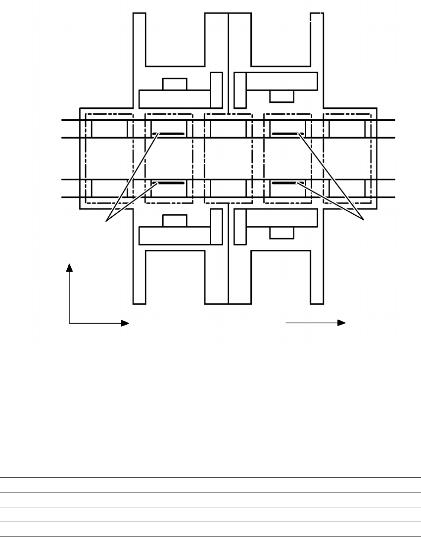
Fig. 2.1 - 1 Arrangement of the ceramic substrate centering units, stationary conveyor side on the right.
2
2.1.1 Possible centering modes
The following centering modes for ceramic substrates may be entered under conveyor mode in
the machine data (real.ma).
2
Direction of transport
Input
area
Location 3
Location 1
Location 2
Gantry 4
Gantry 3
Gantry 2
Gantry 1
Conveyor 2
(left)
Conveyor 1
(right)
Location 4
Processing
area PC1
Intermediate
area
Processing
area PC2
Output
area
Mechanical
ceramic substrate
centering
Mechanical
ceramic substrate
centering
+Y
+X
43
12
Conveyor mode Centering
4 Mechanical substrate centering with normal lighting
5 Multicolor with Y axis clamping only
6 Mechanical ceramic substrate centering with multicolor